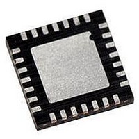
PIC18LF27J53-I/ML Microchip Technology, PIC18LF27J53-I/ML Datasheet - Page 273

PIC18LF27J53-I/ML
Manufacturer Part Number
PIC18LF27J53-I/ML
Description
IC PIC MCU 128KB FLASH 28QFN
Manufacturer
Microchip Technology
Series
PIC® XLP™ 18Fr
Datasheets
1.PIC18LF24J10-ISS.pdf
(32 pages)
2.PIC18F26J13-ISS.pdf
(496 pages)
3.PIC18F26J53-ISS.pdf
(586 pages)
4.PIC18F26J53-ISS.pdf
(12 pages)
Specifications of PIC18LF27J53-I/ML
Core Size
8-Bit
Program Memory Size
128KB (64K x 16)
Core Processor
PIC
Speed
48MHz
Connectivity
I²C, LIN, SPI, UART/USART, USB
Peripherals
Brown-out Detect/Reset, POR, PWM, WDT
Number Of I /o
22
Program Memory Type
FLASH
Ram Size
3.8K x 8
Voltage - Supply (vcc/vdd)
2 V ~ 2.75 V
Data Converters
A/D 10x10b/12b
Oscillator Type
Internal
Operating Temperature
-40°C ~ 85°C
Package / Case
*
Controller Family/series
PIC18
Cpu Speed
48MHz
Digital Ic Case Style
QFN
Supply Voltage Range
1.8V To 3.6V
Embedded Interface Type
I2C, SPI, USART
Rohs Compliant
Yes
Lead Free Status / RoHS Status
Lead free / RoHS Compliant
Eeprom Size
-
Lead Free Status / RoHS Status
Lead free / RoHS Compliant, Lead free / RoHS Compliant
Available stocks
Company
Part Number
Manufacturer
Quantity
Price
Company:
Part Number:
PIC18LF27J53-I/ML
Manufacturer:
ATMEL
Quantity:
101
- PIC18LF24J10-ISS PDF datasheet
- PIC18F26J13-ISS PDF datasheet #2
- PIC18F26J53-ISS PDF datasheet #3
- PIC18F26J53-ISS PDF datasheet #4
- Current page: 273 of 586
- Download datasheet (6Mb)
19.2.2
The timers that are to be used with the capture feature
(Timer1 and/or Timer3) must be running in Timer mode
or Synchronized Counter mode. In Asynchronous
Counter mode, the capture operation may not work.
The timer to be used with each ECCP module is
selected in the CCPTMRS0 register (Register 19-2).
19.2.3
When the Capture mode is changed, a false capture
interrupt may be generated. The user should keep the
CCPxIE interrupt enable bit clear to avoid false interrupts.
The interrupt flag bit, CCPxIF, should also be cleared
following any such change in operating mode.
19.2.4
There are four prescaler settings in Capture mode; they
are specified as part of the operating mode selected by
the mode select bits (CCPxM<3:0>). Whenever the
FIGURE 19-1:
2010 Microchip Technology Inc.
ECCP1 Pin
TIMER1/TIMER3 MODE SELECTION
SOFTWARE INTERRUPT
ECCP PRESCALER
CCP1CON<3:0>
Prescaler
1, 4, 16
CAPTURE MODE OPERATION BLOCK DIAGRAM
Q1:Q4
4
Edge Detect
4
and
Set CCP1IF
Preliminary
C1TSEL0
C1TSEL1
C1TSEL2
C1TSEL0
C1TSEL1
C1TSEL2
PIC18F47J53 FAMILY
ECCP module is turned off, or Capture mode is dis-
abled, the prescaler counter is cleared. This means
that any Reset will clear the prescaler counter.
Switching from one capture prescaler to another may
generate an interrupt. Also, the prescaler counter will
not be cleared; therefore, the first capture may be from
a non-zero prescaler. Example 19-1 provides the
recommended method for switching between capture
prescalers. This example also clears the prescaler
counter and will not generate the “false” interrupt.
EXAMPLE 19-1:
CLRF
MOVLW
MOVWF
ECCP1CON
NEW_CAPT_PS ; Load WREG with the
CCP1CON
CHANGING BETWEEN
CAPTURE PRESCALERS
; Turn ECCP module off
; new prescaler mode
; value and ECCP ON
; Load ECCP1CON with
; this value
TMR3
Enable
TMR1
Enable
CCPR1H
TMR3H
TMR1H
DS39964B-page 273
CCPR1L
TMR1L
TMR3L
Related parts for PIC18LF27J53-I/ML
Image
Part Number
Description
Manufacturer
Datasheet
Request
R

Part Number:
Description:
Manufacturer:
Microchip Technology Inc.
Datasheet:

Part Number:
Description:
Manufacturer:
Microchip Technology Inc.
Datasheet:

Part Number:
Description:
Manufacturer:
Microchip Technology Inc.
Datasheet:

Part Number:
Description:
Manufacturer:
Microchip Technology Inc.
Datasheet:

Part Number:
Description:
Manufacturer:
Microchip Technology Inc.
Datasheet:

Part Number:
Description:
Manufacturer:
Microchip Technology Inc.
Datasheet:

Part Number:
Description:
Manufacturer:
Microchip Technology Inc.
Datasheet:

Part Number:
Description:
Manufacturer:
Microchip Technology Inc.
Datasheet:


