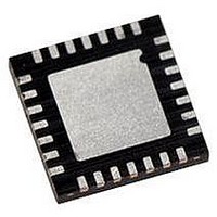
PIC18LF27J53-I/ML Microchip Technology, PIC18LF27J53-I/ML Datasheet - Page 61

PIC18LF27J53-I/ML
Manufacturer Part Number
PIC18LF27J53-I/ML
Description
IC PIC MCU 128KB FLASH 28QFN
Manufacturer
Microchip Technology
Series
PIC® XLP™ 18Fr
Datasheets
1.PIC18LF24J10-ISS.pdf
(32 pages)
2.PIC18F26J13-ISS.pdf
(496 pages)
3.PIC18F26J53-ISS.pdf
(586 pages)
4.PIC18F26J53-ISS.pdf
(12 pages)
Specifications of PIC18LF27J53-I/ML
Core Size
8-Bit
Program Memory Size
128KB (64K x 16)
Core Processor
PIC
Speed
48MHz
Connectivity
I²C, LIN, SPI, UART/USART, USB
Peripherals
Brown-out Detect/Reset, POR, PWM, WDT
Number Of I /o
22
Program Memory Type
FLASH
Ram Size
3.8K x 8
Voltage - Supply (vcc/vdd)
2 V ~ 2.75 V
Data Converters
A/D 10x10b/12b
Oscillator Type
Internal
Operating Temperature
-40°C ~ 85°C
Package / Case
*
Controller Family/series
PIC18
Cpu Speed
48MHz
Digital Ic Case Style
QFN
Supply Voltage Range
1.8V To 3.6V
Embedded Interface Type
I2C, SPI, USART
Rohs Compliant
Yes
Lead Free Status / RoHS Status
Lead free / RoHS Compliant
Eeprom Size
-
Lead Free Status / RoHS Status
Lead free / RoHS Compliant, Lead free / RoHS Compliant
Available stocks
Company
Part Number
Manufacturer
Quantity
Price
Company:
Part Number:
PIC18LF27J53-I/ML
Manufacturer:
ATMEL
Quantity:
101
- PIC18LF24J10-ISS PDF datasheet
- PIC18F26J13-ISS PDF datasheet #2
- PIC18F26J53-ISS PDF datasheet #3
- PIC18F26J53-ISS PDF datasheet #4
- Current page: 61 of 586
- Download datasheet (6Mb)
4.7
The Ultra Low-Power Wake-up (ULPWU) on RA0 allows
a slow falling voltage to generate an interrupt-on-change
without excess current consumption.
Follow these steps to use this feature:
1.
2.
3.
4.
5.
6.
7.
8.
2010 Microchip Technology Inc.
Configure a remappable output pin to output the
ULPOUT signal.
Map an INTx interrupt-on-change input function to
the same pin as used for the ULPOUT output func-
tion. Alternatively, in step 1, configure ULPOUT to
output onto a PORTB interrupt-on-change pin.
Charge the capacitor on RA0 by configuring the
RA0 pin to an output and setting it to ‘1’.
Enable interrupt-on-change (PIE bit) for the
corresponding pin selected in step 2.
Stop charging the capacitor by configuring RA0
as an input.
Discharge the capacitor by setting the ULPEN
and ULPSINK bits in the WDTCON register.
Configure Sleep mode.
Enter Sleep mode.
Ultra Low-Power Wake-up
Preliminary
PIC18F47J53 FAMILY
When the voltage on RA0 drops below V
will be generated, which will cause the device to
wake-up and execute the next instruction.
This feature provides a low-power technique for
periodically waking up the device from Sleep mode.
The time-out is dependent on the discharge time of the
RC circuit on RA0.
When the ULPWU module causes the device to
wake-up from Sleep mode, the ULPLVL (WDTCON<5>)
bit is set. When the ULPWU module causes the device
to
(DSWAKEL<5>) bit is set. Software can check these bits
upon wake-up to determine the wake-up source. Also in
Sleep mode, only the remappable output function,
ULPWU, will output this bit value to an RPn pin for
externally detecting wake-up events.
See Example 4-1 for initializing the ULPWU module.
Note:
wake-up
For module related bit definitions, see the
WDTCON
“Watchdog Timer (WDT)” and the
DSWAKEL register (Register 4-6).
from
Deep
register
Sleep,
in
DS39964B-page 61
IL
Section 28.2
the
, an interrupt
DSULP
Related parts for PIC18LF27J53-I/ML
Image
Part Number
Description
Manufacturer
Datasheet
Request
R

Part Number:
Description:
Manufacturer:
Microchip Technology Inc.
Datasheet:

Part Number:
Description:
Manufacturer:
Microchip Technology Inc.
Datasheet:

Part Number:
Description:
Manufacturer:
Microchip Technology Inc.
Datasheet:

Part Number:
Description:
Manufacturer:
Microchip Technology Inc.
Datasheet:

Part Number:
Description:
Manufacturer:
Microchip Technology Inc.
Datasheet:

Part Number:
Description:
Manufacturer:
Microchip Technology Inc.
Datasheet:

Part Number:
Description:
Manufacturer:
Microchip Technology Inc.
Datasheet:

Part Number:
Description:
Manufacturer:
Microchip Technology Inc.
Datasheet:


