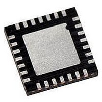
PIC18LF27J53-I/ML Microchip Technology, PIC18LF27J53-I/ML Datasheet - Page 425

PIC18LF27J53-I/ML
Manufacturer Part Number
PIC18LF27J53-I/ML
Description
IC PIC MCU 128KB FLASH 28QFN
Manufacturer
Microchip Technology
Series
PIC® XLP™ 18Fr
Datasheets
1.PIC18LF24J10-ISS.pdf
(32 pages)
2.PIC18F26J13-ISS.pdf
(496 pages)
3.PIC18F26J53-ISS.pdf
(586 pages)
4.PIC18F26J53-ISS.pdf
(12 pages)
Specifications of PIC18LF27J53-I/ML
Core Size
8-Bit
Program Memory Size
128KB (64K x 16)
Core Processor
PIC
Speed
48MHz
Connectivity
I²C, LIN, SPI, UART/USART, USB
Peripherals
Brown-out Detect/Reset, POR, PWM, WDT
Number Of I /o
22
Program Memory Type
FLASH
Ram Size
3.8K x 8
Voltage - Supply (vcc/vdd)
2 V ~ 2.75 V
Data Converters
A/D 10x10b/12b
Oscillator Type
Internal
Operating Temperature
-40°C ~ 85°C
Package / Case
*
Controller Family/series
PIC18
Cpu Speed
48MHz
Digital Ic Case Style
QFN
Supply Voltage Range
1.8V To 3.6V
Embedded Interface Type
I2C, SPI, USART
Rohs Compliant
Yes
Lead Free Status / RoHS Status
Lead free / RoHS Compliant
Eeprom Size
-
Lead Free Status / RoHS Status
Lead free / RoHS Compliant, Lead free / RoHS Compliant
Available stocks
Company
Part Number
Manufacturer
Quantity
Price
Company:
Part Number:
PIC18LF27J53-I/ML
Manufacturer:
ATMEL
Quantity:
101
- PIC18LF24J10-ISS PDF datasheet
- PIC18F26J13-ISS PDF datasheet #2
- PIC18F26J53-ISS PDF datasheet #3
- PIC18F26J53-ISS PDF datasheet #4
- Current page: 425 of 586
- Download datasheet (6Mb)
27.0
The Charge Time Measurement Unit (CTMU) is a
flexible analog module that provides accurate differen-
tial time measurement between pulse sources, as well
as asynchronous pulse generation. By working with
other on-chip analog modules, the CTMU can be used
to precisely measure time, measure capacitance,
measure relative changes in capacitance or generate
output pulses with a specific time delay. The CTMU is
ideal for interfacing with capacitive-based sensors.
The module includes the following key features:
• Up to 13 channels available for capacitive or time
• On-chip precision current source
• Four-edge input trigger sources
• Polarity control for each edge source
FIGURE 27-1:
2010 Microchip Technology Inc.
measurement input
CHARGE TIME
MEASUREMENT UNIT (CTMU)
ECCP1
CTED1
CTED2
Timer1
CTMU BLOCK DIAGRAM
EDGEN
EDGSEQEN
EDG1SELx
EDG1POL
EDG2SELx
EDG2POL
Control
Edge
Logic
EDG1STAT
EDG2STAT
A/D Converter
Preliminary
Current Source
CTMUICON
CTMUCON
Current
Control
Comparator 2
PIC18F47J53 FAMILY
Input
ITRIM<5:0>
IRNG<1:0>
• Control of edge sequence
• Control of response to edges
• Time measurement resolution of 1 nanosecond
• High precision time measurement
• Time delay of external or internal signal
• Accurate current source suitable for capacitive
The CTMU works in conjunction with the A/D Converter
to provide up to 13 channels for time or charge
measurement, depending on the specific device and
the number of A/D channels available. When config-
ured for time delay, the CTMU is connected to one of
the analog comparators. The level-sensitive input edge
sources can be selected from four sources: two
external inputs, Timer1 or Output Compare Module 1.
Figure 27-1 provides a block diagram of the CTMU.
asynchronous to system clock
measurement
Comparator 2 Output
Generator
Control
CTMU
Logic
Pulse
TGEN
IDISSEN
DS39964B-page 425
CTPLS
Related parts for PIC18LF27J53-I/ML
Image
Part Number
Description
Manufacturer
Datasheet
Request
R

Part Number:
Description:
Manufacturer:
Microchip Technology Inc.
Datasheet:

Part Number:
Description:
Manufacturer:
Microchip Technology Inc.
Datasheet:

Part Number:
Description:
Manufacturer:
Microchip Technology Inc.
Datasheet:

Part Number:
Description:
Manufacturer:
Microchip Technology Inc.
Datasheet:

Part Number:
Description:
Manufacturer:
Microchip Technology Inc.
Datasheet:

Part Number:
Description:
Manufacturer:
Microchip Technology Inc.
Datasheet:

Part Number:
Description:
Manufacturer:
Microchip Technology Inc.
Datasheet:

Part Number:
Description:
Manufacturer:
Microchip Technology Inc.
Datasheet:


