DS72011RB120FPV Renesas Electronics America, DS72011RB120FPV Datasheet - Page 220
DS72011RB120FPV
Manufacturer Part Number
DS72011RB120FPV
Description
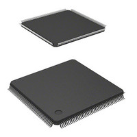
IC SH7201 MPU ROMLESS 176LQFP
Manufacturer
Renesas Electronics America
Series
SuperH® SH7200r
Datasheet
1.R0K572011S000BE.pdf
(1222 pages)
Specifications of DS72011RB120FPV
Core Size
32-Bit
Core Processor
SH-2A
Speed
120MHz
Connectivity
CAN, EBI/EMI, FIFO, I²C, SCI, Serial Sound
Peripherals
DMA, POR, PWM, WDT
Number Of I /o
104
Program Memory Type
ROMless
Ram Size
32K x 8
Voltage - Supply (vcc/vdd)
3 V ~ 3.6 V
Data Converters
A/D 8x10b; D/A 2x8b
Oscillator Type
Internal
Operating Temperature
-20°C ~ 70°C
Package / Case
176-LQFP
No. Of I/o's
109
Ram Memory Size
32KB
Cpu Speed
120MHz
Digital Ic Case Style
LQFP
Supply Voltage Range
3V To 3.6V
Operating Temperature Range
-20°C To +70°C
Embedded Interface Type
I2C, SSI
Rohs Compliant
Yes
Lead Free Status / RoHS Status
Lead free / RoHS Compliant
For Use With
R0K572011S000BE - KIT STARTER FOR SH7201HS0005KCU11H - EMULATOR E10A-USB H8S(X),SH2(A)
Eeprom Size
-
Program Memory Size
-
Lead Free Status / RoHS Status
Lead free / RoHS Compliant, Lead free / RoHS Compliant
Available stocks
Company
Part Number
Manufacturer
Quantity
Price
Company:

Part Number:
DS72011RB120FPV
Manufacturer:
Renesas Electronics America
Quantity:
10 000


Section 8 Cache
(2)
In write-back mode, an external bus cycle starts when a write miss occurs, and the entry is
updated. The way to be replaced follows table 8.4. When the U bit of the entry to be replaced is 1,
the cache update cycle starts after the entry is transferred to the write-back buffer. Data is written
to the cache, the U bit is set to 1, and the V bit is set to 1. LRU is updated so that the replaced way
becomes the latest. After the cache completes its update cycle, the write-back buffer writes the
entry back to the memory. The write-back unit is 16 bytes.
In write-through mode, no write to cache occurs in a write miss; the write is only to the external
memory.
8.3.5
When the U bit of the entry to be replaced in the write-back mode is 1, it must be written back to
the external memory. To increase performance, the entry to be replaced is first transferred to the
write-back buffer and fetching of new entries to the cache takes priority over writing back to the
external memory. After the cache completes to fetch the new entry, the write-back buffer writes
the entry back to external memory. During the write-back cycles, the cache can be accessed. The
write-back buffer can hold one line of cache data (16 bytes) and its physical address. Figure 8.3
shows the configuration of the write-back buffer.
Operations in sections 8.3.2 to 8.3.5 are compiled in table 8.8
Page 192 of 1190
Write Miss
A (31 to 4):
Longword 0 to 3: One line of cache data to be written to external memory
A (31 to 4)
Write-Back Buffer (Only for Operand Cache)
Physical address written to external memory (upper three bits are 0)
Figure 8.3 Write-Back Buffer Configuration
Longword 0
Longword 1
Longword 2
R01UH0026EJ0300 Rev. 3.00
Longword 3
SH7201 Group
Sep 24, 2010
Related parts for DS72011RB120FPV
Image
Part Number
Description
Manufacturer
Datasheet
Request
R

Part Number:
Description:
KIT STARTER FOR M16C/29
Manufacturer:
Renesas Electronics America
Datasheet:

Part Number:
Description:
KIT STARTER FOR R8C/2D
Manufacturer:
Renesas Electronics America
Datasheet:

Part Number:
Description:
R0K33062P STARTER KIT
Manufacturer:
Renesas Electronics America
Datasheet:

Part Number:
Description:
KIT STARTER FOR R8C/23 E8A
Manufacturer:
Renesas Electronics America
Datasheet:

Part Number:
Description:
KIT STARTER FOR R8C/25
Manufacturer:
Renesas Electronics America
Datasheet:

Part Number:
Description:
KIT STARTER H8S2456 SHARPE DSPLY
Manufacturer:
Renesas Electronics America
Datasheet:

Part Number:
Description:
KIT STARTER FOR R8C38C
Manufacturer:
Renesas Electronics America
Datasheet:

Part Number:
Description:
KIT STARTER FOR R8C35C
Manufacturer:
Renesas Electronics America
Datasheet:

Part Number:
Description:
KIT STARTER FOR R8CL3AC+LCD APPS
Manufacturer:
Renesas Electronics America
Datasheet:
Part Number:
Description:
KIT STARTER FOR RX610
Manufacturer:
Renesas Electronics America
Datasheet:

Part Number:
Description:
KIT STARTER FOR R32C/118
Manufacturer:
Renesas Electronics America
Datasheet:

Part Number:
Description:
KIT DEV RSK-R8C/26-29
Manufacturer:
Renesas Electronics America
Datasheet:

Part Number:
Description:
KIT STARTER FOR SH7124
Manufacturer:
Renesas Electronics America
Datasheet:

Part Number:
Description:
KIT STARTER FOR H8SX/1622
Manufacturer:
Renesas Electronics America
Datasheet:

Part Number:
Description:
KIT DEV FOR SH7203
Manufacturer:
Renesas Electronics America
Datasheet: