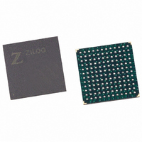
EZ80F91NA050SC Zilog, EZ80F91NA050SC Datasheet - Page 136

EZ80F91NA050SC
Manufacturer Part Number
EZ80F91NA050SC
Description
IC ACCLAIM MCU 256KB 144-BGA
Manufacturer
Zilog
Series
eZ80® Acclaim!®r
Specifications of EZ80F91NA050SC
Core Processor
Z8
Core Size
8-Bit
Speed
50MHz
Connectivity
Ethernet, I²C, IrDA, SPI, UART/USART
Peripherals
Brown-out Detect/Reset, POR, PWM, WDT
Number Of I /o
32
Program Memory Size
256KB (256K x 8)
Program Memory Type
FLASH
Ram Size
16K x 8
Voltage - Supply (vcc/vdd)
3 V ~ 3.6 V
Oscillator Type
Internal
Operating Temperature
0°C ~ 70°C
Package / Case
144-LBGA
Data Bus Width
8 bit
Maximum Clock Frequency
50 MHz
Data Ram Size
16 KB
Number Of Programmable I/os
32
Number Of Timers
16 Bit
Operating Supply Voltage
3 V to 3.6 V
Mounting Style
SMD/SMT
Height
1.5 mm
Length
13 mm
Maximum Operating Temperature
+ 70 C
Minimum Operating Temperature
0 C
Width
13 mm
For Use With
269-4712 - KIT DEV ENCORE 32 SERIES269-4671 - BOARD ZDOTS SBC Z80ACCLAIM PLUS269-4561 - KIT DEV FOR EZ80F91 W/C-COMPILER269-4560 - KIT DEV FOR EZ80F91 W/C-COMPILER
Lead Free Status / RoHS Status
Contains lead / RoHS non-compliant
Eeprom Size
-
Data Converters
-
Lead Free Status / Rohs Status
No RoHS Version Available
Other names
269-3251
Available stocks
Company
Part Number
Manufacturer
Quantity
Price
- Current page: 136 of 384
- Download datasheet (3Mb)
PS019215-0910
•
•
•
•
Timer 3 consists of three specialty modes. Each of these modes are enabled using bits in
their respective control registers (TMR3_CAP_CTL, TMR3_OC_CTL1,
TMR3_PWM_CTL1). When PWM mode is enabled, the OUTPUT COMPARE and
INPUT CAPTURE modes are not available. This instance is due to address space sharing
requirements. However, INPUT CAPTURE and OUTPUT COMPARE modes run
simultaneously.
Timers with specialty modes offer multiple ways to generate an interrupt. When the inter-
rupt controller services a timer interrupt, the software must read the timers interrupt iden-
tification register (TMRx_IIR) to determine the causes for an interrupt request. This
register is cleared each time it is read, allowing subsequent events to be identified without
interference from prior events.
Event Counter
When a timer is configured to take its input from a port input pin (ECx), it functions as an
event counter. For event counting, the clock prescaler is automatically bypassed and edges
(events) cause the timer to decrement. You must select the rising or the falling edge for
counting. Also, the port pins must be configured as inputs.
Input sampling on the port pins results in the counter being updated on the third rising
edge of the system clock after the edge event occurs at the port pin. Due to sampling, the
frequency of the event input is limited to one-half the system clock frequency under ideal
conditions. In practice, the event frequency must be less than this value due to duty cycle
variation and system clock jitter.
This EVENT COUNT mode is identical to basic timer operation, except for the clock
source. Therefore, interrupts are managed in the same manner.
Timer 0
–
Timer 1
–
–
Timer 2
–
Timer 3
–
–
–
No special functions
One event counter (EC0)
Two input captures (IC0 and IC1)
One event counter (EC1)
Two input captures (IC2 and IC3)
Four output compares (OC0, OC1, OC2, and OC3)
Four PWM outputs (PWM0, PWM1, PWM2, and PWM3)
Programmable Reload Timers
Product Specification
eZ80F91 MCU
127
Related parts for EZ80F91NA050SC
Image
Part Number
Description
Manufacturer
Datasheet
Request
R

Part Number:
Description:
Communication Controllers, ZILOG INTELLIGENT PERIPHERAL CONTROLLER (ZIP)
Manufacturer:
Zilog, Inc.
Datasheet:

Part Number:
Description:
KIT DEV FOR Z8 ENCORE 16K TO 64K
Manufacturer:
Zilog
Datasheet:

Part Number:
Description:
KIT DEV Z8 ENCORE XP 28-PIN
Manufacturer:
Zilog
Datasheet:

Part Number:
Description:
DEV KIT FOR Z8 ENCORE 8K/4K
Manufacturer:
Zilog
Datasheet:

Part Number:
Description:
KIT DEV Z8 ENCORE XP 28-PIN
Manufacturer:
Zilog
Datasheet:

Part Number:
Description:
DEV KIT FOR Z8 ENCORE 4K TO 8K
Manufacturer:
Zilog
Datasheet:

Part Number:
Description:
CMOS Z8 microcontroller. ROM 16 Kbytes, RAM 256 bytes, speed 16 MHz, 32 lines I/O, 3.0V to 5.5V
Manufacturer:
Zilog, Inc.
Datasheet:

Part Number:
Description:
Low-cost microcontroller. 512 bytes ROM, 61 bytes RAM, 8 MHz
Manufacturer:
Zilog, Inc.
Datasheet:

Part Number:
Description:
Z8 4K OTP Microcontroller
Manufacturer:
Zilog, Inc.
Datasheet:

Part Number:
Description:
CMOS SUPER8 ROMLESS MCU
Manufacturer:
Zilog, Inc.
Datasheet:

Part Number:
Description:
SL1866 CMOSZ8 OTP Microcontroller
Manufacturer:
Zilog, Inc.
Datasheet:

Part Number:
Description:
SL1866 CMOSZ8 OTP Microcontroller
Manufacturer:
Zilog, Inc.
Datasheet:

Part Number:
Description:
OTP (KB) = 1, RAM = 125, Speed = 12, I/O = 14, 8-bit Timers = 2, Comm Interfaces Other Features = Por, LV Protect, Voltage = 4.5-5.5V
Manufacturer:
Zilog, Inc.
Datasheet:

Part Number:
Description:
Manufacturer:
Zilog, Inc.
Datasheet:


