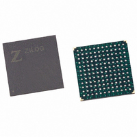
EZ80F91NA050SC Zilog, EZ80F91NA050SC Datasheet - Page 187

EZ80F91NA050SC
Manufacturer Part Number
EZ80F91NA050SC
Description
IC ACCLAIM MCU 256KB 144-BGA
Manufacturer
Zilog
Series
eZ80® Acclaim!®r
Specifications of EZ80F91NA050SC
Core Processor
Z8
Core Size
8-Bit
Speed
50MHz
Connectivity
Ethernet, I²C, IrDA, SPI, UART/USART
Peripherals
Brown-out Detect/Reset, POR, PWM, WDT
Number Of I /o
32
Program Memory Size
256KB (256K x 8)
Program Memory Type
FLASH
Ram Size
16K x 8
Voltage - Supply (vcc/vdd)
3 V ~ 3.6 V
Oscillator Type
Internal
Operating Temperature
0°C ~ 70°C
Package / Case
144-LBGA
Data Bus Width
8 bit
Maximum Clock Frequency
50 MHz
Data Ram Size
16 KB
Number Of Programmable I/os
32
Number Of Timers
16 Bit
Operating Supply Voltage
3 V to 3.6 V
Mounting Style
SMD/SMT
Height
1.5 mm
Length
13 mm
Maximum Operating Temperature
+ 70 C
Minimum Operating Temperature
0 C
Width
13 mm
For Use With
269-4712 - KIT DEV ENCORE 32 SERIES269-4671 - BOARD ZDOTS SBC Z80ACCLAIM PLUS269-4561 - KIT DEV FOR EZ80F91 W/C-COMPILER269-4560 - KIT DEV FOR EZ80F91 W/C-COMPILER
Lead Free Status / RoHS Status
Contains lead / RoHS non-compliant
Eeprom Size
-
Data Converters
-
Lead Free Status / Rohs Status
No RoHS Version Available
Other names
269-3251
Available stocks
Company
Part Number
Manufacturer
Quantity
Price
- Current page: 187 of 384
- Download datasheet (3Mb)
PS019215-0910
Note:
UART Interrupts
There are six different sources of interrupts from the UART. The six sources of interrupts
are:
•
•
•
UART Transmitter Interrupt
A Transmitter Hold Register Empty interrupt is generated if there is no data available in
the hold register. By the same token, a transmission complete interrupt is generated after
the data in the shift register is sent. Both interrupts are disabled using individual interrupt
enable bits, or cleared by writing data into the UARTx_THR register.
UART Receiver Interrupts
A receiver interrupt is generated by three possible events. The first event, a receiver data
ready interrupt event, indicates that one or more data bytes are received and are ready to
be read. Next, this interrupt is generated if the number of bytes in the receiver FIFO is
greater than or equal to the trigger level. If the FIFO is not enabled, the interrupt is gener-
ated if the receive buffer contains a data byte. This interrupt is cleared by reading the
UARTx_RBR.
The second interrupt source is the receiver time-out. A receiver time-out interrupt is gen-
erated when there are fewer data bytes in the receiver FIFO than the trigger level and there
are no Reads and Writes to or from the receiver FIFO for four consecutive byte times.
When the receiver time-out interrupt is generated, it is cleared only after emptying the
entire receive FIFO.
The first two interrupt sources from the receiver (data ready and time-out) share an inter-
rupt enable bit. The third source of a receiver interrupt is a line status error, indicating an
error in byte reception. This error results from:
•
For 9-bit data, incorrect parity indicates detection of an address byte.
•
•
•
Transmitter (two different interrupts)
Receiver (three different interrupts)
Modem status
Incorrect received parity.
Incorrect framing (that is, the stop bit) is not detected by receiver at the end of the byte.
Receiver overrun condition.
A BREAK condition being detected on the receive data input.
Universal Asynchronous Receiver/Transmitter
Product Specification
eZ80F91 MCU
178
Related parts for EZ80F91NA050SC
Image
Part Number
Description
Manufacturer
Datasheet
Request
R

Part Number:
Description:
Communication Controllers, ZILOG INTELLIGENT PERIPHERAL CONTROLLER (ZIP)
Manufacturer:
Zilog, Inc.
Datasheet:

Part Number:
Description:
KIT DEV FOR Z8 ENCORE 16K TO 64K
Manufacturer:
Zilog
Datasheet:

Part Number:
Description:
KIT DEV Z8 ENCORE XP 28-PIN
Manufacturer:
Zilog
Datasheet:

Part Number:
Description:
DEV KIT FOR Z8 ENCORE 8K/4K
Manufacturer:
Zilog
Datasheet:

Part Number:
Description:
KIT DEV Z8 ENCORE XP 28-PIN
Manufacturer:
Zilog
Datasheet:

Part Number:
Description:
DEV KIT FOR Z8 ENCORE 4K TO 8K
Manufacturer:
Zilog
Datasheet:

Part Number:
Description:
CMOS Z8 microcontroller. ROM 16 Kbytes, RAM 256 bytes, speed 16 MHz, 32 lines I/O, 3.0V to 5.5V
Manufacturer:
Zilog, Inc.
Datasheet:

Part Number:
Description:
Low-cost microcontroller. 512 bytes ROM, 61 bytes RAM, 8 MHz
Manufacturer:
Zilog, Inc.
Datasheet:

Part Number:
Description:
Z8 4K OTP Microcontroller
Manufacturer:
Zilog, Inc.
Datasheet:

Part Number:
Description:
CMOS SUPER8 ROMLESS MCU
Manufacturer:
Zilog, Inc.
Datasheet:

Part Number:
Description:
SL1866 CMOSZ8 OTP Microcontroller
Manufacturer:
Zilog, Inc.
Datasheet:

Part Number:
Description:
SL1866 CMOSZ8 OTP Microcontroller
Manufacturer:
Zilog, Inc.
Datasheet:

Part Number:
Description:
OTP (KB) = 1, RAM = 125, Speed = 12, I/O = 14, 8-bit Timers = 2, Comm Interfaces Other Features = Por, LV Protect, Voltage = 4.5-5.5V
Manufacturer:
Zilog, Inc.
Datasheet:

Part Number:
Description:
Manufacturer:
Zilog, Inc.
Datasheet:


