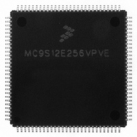
MC9S12E256VPVE Freescale Semiconductor, MC9S12E256VPVE Datasheet - Page 172

MC9S12E256VPVE
Manufacturer Part Number
MC9S12E256VPVE
Description
IC MCU 256K FLASH 25MHZ 112-LQFP
Manufacturer
Freescale Semiconductor
Series
HCS12r
Datasheet
1.MC9S12E256CFUE.pdf
(602 pages)
Specifications of MC9S12E256VPVE
Core Processor
HCS12
Core Size
16-Bit
Speed
25MHz
Connectivity
EBI/EMI, I²C, SCI, SPI
Peripherals
POR, PWM, WDT
Number Of I /o
91
Program Memory Size
256KB (256K x 8)
Program Memory Type
FLASH
Ram Size
16K x 8
Voltage - Supply (vcc/vdd)
2.35 V ~ 2.75 V
Data Converters
A/D 16x10b; D/A 2x8b
Oscillator Type
Internal
Operating Temperature
-40°C ~ 105°C
Package / Case
112-LQFP
Processor Series
S12E
Core
HCS12
Data Bus Width
16 bit
Data Ram Size
16 KB
Interface Type
I2C/SCI/SPI
Maximum Clock Frequency
50 MHz
Number Of Programmable I/os
92
Number Of Timers
12
Maximum Operating Temperature
+ 105 C
Mounting Style
SMD/SMT
3rd Party Development Tools
EWHCS12
Minimum Operating Temperature
- 40 C
On-chip Adc
16-ch x 10-bit
On-chip Dac
2-ch x 8-bit
For Use With
M68EVB912E128 - BOARD EVAL FOR MC9S12E128/64
Lead Free Status / RoHS Status
Lead free / RoHS Compliant
Eeprom Size
-
Lead Free Status / Rohs Status
Lead free / RoHS Compliant
Available stocks
Company
Part Number
Manufacturer
Quantity
Price
Company:
Part Number:
MC9S12E256VPVE
Manufacturer:
Freescale Semiconductor
Quantity:
10 000
- Current page: 172 of 602
- Download datasheet (4Mb)
Chapter 4 Clocks and Reset Generator (CRGV4)
4.3.2.4
This register provides CRG status bits and flags.
Read: anytime
Write: refer to each bit for individual write conditions
172
1. PORF is set to 1 when a power-on reset occurs. Unaffected by system reset.
2. LVRF is set to 1 when a low-voltage reset occurs. Unaffected by system reset.
LOCKIF
TRACK
Reset
PORF
LOCK
Field
LVRF
RTIF
7
6
5
4
3
2
W
R
RTIF
Real-Time Interrupt Flag — RTIF is set to 1 at the end of the RTI period. This flag can only be cleared by writing
a 1. Writing a 0 has no effect. If enabled (RTIE = 1), RTIF causes an interrupt request.
0 RTI time-out has not yet occurred.
1 RTI time-out has occurred.
Power-on Reset Flag — PORF is set to 1 when a power-on reset occurs. This flag can only be cleared by writing
a 1. Writing a 0 has no effect.
0 Power-on reset has not occurred.
1 Power-on reset has occurred.
Low-Voltage Reset Flag — If low voltage reset feature is not available (see
Overview
flag can only be cleared by writing a 1. Writing a 0 has no effect.
0 Low voltage reset has not occurred.
1 Low voltage reset has occurred.
PLL Lock Interrupt Flag — LOCKIF is set to 1 when LOCK status bit changes. This flag can only be cleared by
writing a 1. Writing a 0 has no effect.If enabled (LOCKIE = 1), LOCKIF causes an interrupt request.
0 No change in LOCK bit.
1 LOCK bit has changed.
Lock Status Bit — LOCK reflects the current state of PLL lock condition. This bit is cleared in self-clock mode.
Writes have no effect.
0 PLL VCO is not within the desired tolerance of the target frequency.
1 PLL VCO is within the desired tolerance of the target frequency.
Track Status Bit — TRACK reflects the current state of PLL track condition. This bit is cleared in self-clock mode.
Writes have no effect.
0 Acquisition mode status.
1 Tracking mode status.
CRG Flags Register (CRGFLG)
0
7
= Unimplemented or Reserved
(MC9S12E256DGV1)”), LVRF always reads 0. LVRF is set to 1 when a low voltage reset occurs. This
Note 1
PORF
6
Figure 4-7. CRG Flag Register (CRGFLG)
Table 4-2. CRGFLG Field Descriptions
Note 2
LVRF
MC9S12E256 Data Sheet, Rev. 1.08
5
LOCKIF
0
4
Description
LOCK
3
0
TRACK
0
2
Chapter 1, “MC9S12E256 Device
Freescale Semiconductor
SCMIF
0
1
SCM
0
0
Related parts for MC9S12E256VPVE
Image
Part Number
Description
Manufacturer
Datasheet
Request
R
Part Number:
Description:
Manufacturer:
Freescale Semiconductor, Inc
Datasheet:
Part Number:
Description:
Manufacturer:
Freescale Semiconductor, Inc
Datasheet:
Part Number:
Description:
Manufacturer:
Freescale Semiconductor, Inc
Datasheet:
Part Number:
Description:
Manufacturer:
Freescale Semiconductor, Inc
Datasheet:
Part Number:
Description:
Manufacturer:
Freescale Semiconductor, Inc
Datasheet:
Part Number:
Description:
Manufacturer:
Freescale Semiconductor, Inc
Datasheet:
Part Number:
Description:
Manufacturer:
Freescale Semiconductor, Inc
Datasheet:
Part Number:
Description:
Manufacturer:
Freescale Semiconductor, Inc
Datasheet:
Part Number:
Description:
Manufacturer:
Freescale Semiconductor, Inc
Datasheet:
Part Number:
Description:
Manufacturer:
Freescale Semiconductor, Inc
Datasheet:
Part Number:
Description:
Manufacturer:
Freescale Semiconductor, Inc
Datasheet:
Part Number:
Description:
Manufacturer:
Freescale Semiconductor, Inc
Datasheet:
Part Number:
Description:
Manufacturer:
Freescale Semiconductor, Inc
Datasheet:
Part Number:
Description:
Manufacturer:
Freescale Semiconductor, Inc
Datasheet:
Part Number:
Description:
Manufacturer:
Freescale Semiconductor, Inc
Datasheet:


