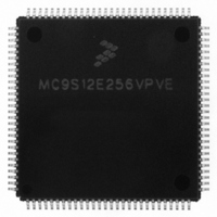
MC9S12E256VPVE Freescale Semiconductor, MC9S12E256VPVE Datasheet - Page 192

MC9S12E256VPVE
Manufacturer Part Number
MC9S12E256VPVE
Description
IC MCU 256K FLASH 25MHZ 112-LQFP
Manufacturer
Freescale Semiconductor
Series
HCS12r
Datasheet
1.MC9S12E256CFUE.pdf
(602 pages)
Specifications of MC9S12E256VPVE
Core Processor
HCS12
Core Size
16-Bit
Speed
25MHz
Connectivity
EBI/EMI, I²C, SCI, SPI
Peripherals
POR, PWM, WDT
Number Of I /o
91
Program Memory Size
256KB (256K x 8)
Program Memory Type
FLASH
Ram Size
16K x 8
Voltage - Supply (vcc/vdd)
2.35 V ~ 2.75 V
Data Converters
A/D 16x10b; D/A 2x8b
Oscillator Type
Internal
Operating Temperature
-40°C ~ 105°C
Package / Case
112-LQFP
Processor Series
S12E
Core
HCS12
Data Bus Width
16 bit
Data Ram Size
16 KB
Interface Type
I2C/SCI/SPI
Maximum Clock Frequency
50 MHz
Number Of Programmable I/os
92
Number Of Timers
12
Maximum Operating Temperature
+ 105 C
Mounting Style
SMD/SMT
3rd Party Development Tools
EWHCS12
Minimum Operating Temperature
- 40 C
On-chip Adc
16-ch x 10-bit
On-chip Dac
2-ch x 8-bit
For Use With
M68EVB912E128 - BOARD EVAL FOR MC9S12E128/64
Lead Free Status / RoHS Status
Lead free / RoHS Compliant
Eeprom Size
-
Lead Free Status / Rohs Status
Lead free / RoHS Compliant
Available stocks
Company
Part Number
Manufacturer
Quantity
Price
Company:
Part Number:
MC9S12E256VPVE
Manufacturer:
Freescale Semiconductor
Quantity:
10 000
- Current page: 192 of 602
- Download datasheet (4Mb)
Chapter 4 Clocks and Reset Generator (CRGV4)
4.4.10
All clocks are stopped in STOP mode, dependent of the setting of the PCE, PRE and PSTP bit. The
oscillator is disabled in STOP mode unless the PSTP bit is set. All counters and dividers remain frozen but
do not initialize. If the PRE or PCE bits are set, the RTI or COP continues to run in pseudo-stop mode. In
addition to disabling system and core clocks the CRG requests other functional units of the MCU (e.g.
voltage-regulator) to enter their individual power-saving modes (if available). This is the main difference
between pseudo-stop mode and wait mode.
After executing the STOP instruction the core requests the CRG to switch the MCU into stop mode. If the
PLLSEL bit remains set when entering stop mode, the CRG will switch the system and core clocks to
OSCCLK by clearing the PLLSEL bit. Then the CRG disables the PLL, disables the core clock and finally
disables the remaining system clocks. As soon as all clocks are switched off, stop mode is active.
If pseudo-stop mode (PSTP = 1) is entered from self-clock mode the CRG will continue to check the clock
quality until clock check is successful. The PLL and the voltage regulator (VREG) will remain enabled. If
full stop mode (PSTP = 0) is entered from self-clock mode an ongoing clock quality check will be stopped.
A complete timeout window check will be started when stop mode is exited again.
Wake-up from stop mode also depends on the setting of the PSTP bit.
192
CME
1
SCME
1
Low-Power Operation in Stop Mode
SCMIE
1
Table 4-11. Outcome of Clock Loss in Wait Mode (continued)
Clock failure -->
– VREG enabled,
– PLL enabled,
– SCM activated,
– Start Clock Quality Check,
– SCMIF set.
SCMIF generates Self-Clock Mode wakeup interrupt.
– Exit Wait Mode in SCM using PLL clock (f
– Continue to perform a additional Clock Quality Checks until OSCCLK
is o.k. again.
MC9S12E256 Data Sheet, Rev. 1.08
CRG Actions
SCM
) as system clock,
Freescale Semiconductor
Related parts for MC9S12E256VPVE
Image
Part Number
Description
Manufacturer
Datasheet
Request
R
Part Number:
Description:
Manufacturer:
Freescale Semiconductor, Inc
Datasheet:
Part Number:
Description:
Manufacturer:
Freescale Semiconductor, Inc
Datasheet:
Part Number:
Description:
Manufacturer:
Freescale Semiconductor, Inc
Datasheet:
Part Number:
Description:
Manufacturer:
Freescale Semiconductor, Inc
Datasheet:
Part Number:
Description:
Manufacturer:
Freescale Semiconductor, Inc
Datasheet:
Part Number:
Description:
Manufacturer:
Freescale Semiconductor, Inc
Datasheet:
Part Number:
Description:
Manufacturer:
Freescale Semiconductor, Inc
Datasheet:
Part Number:
Description:
Manufacturer:
Freescale Semiconductor, Inc
Datasheet:
Part Number:
Description:
Manufacturer:
Freescale Semiconductor, Inc
Datasheet:
Part Number:
Description:
Manufacturer:
Freescale Semiconductor, Inc
Datasheet:
Part Number:
Description:
Manufacturer:
Freescale Semiconductor, Inc
Datasheet:
Part Number:
Description:
Manufacturer:
Freescale Semiconductor, Inc
Datasheet:
Part Number:
Description:
Manufacturer:
Freescale Semiconductor, Inc
Datasheet:
Part Number:
Description:
Manufacturer:
Freescale Semiconductor, Inc
Datasheet:
Part Number:
Description:
Manufacturer:
Freescale Semiconductor, Inc
Datasheet:


