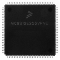
MC9S12E256VPVE Freescale Semiconductor, MC9S12E256VPVE Datasheet - Page 294

MC9S12E256VPVE
Manufacturer Part Number
MC9S12E256VPVE
Description
IC MCU 256K FLASH 25MHZ 112-LQFP
Manufacturer
Freescale Semiconductor
Series
HCS12r
Datasheet
1.MC9S12E256CFUE.pdf
(602 pages)
Specifications of MC9S12E256VPVE
Core Processor
HCS12
Core Size
16-Bit
Speed
25MHz
Connectivity
EBI/EMI, I²C, SCI, SPI
Peripherals
POR, PWM, WDT
Number Of I /o
91
Program Memory Size
256KB (256K x 8)
Program Memory Type
FLASH
Ram Size
16K x 8
Voltage - Supply (vcc/vdd)
2.35 V ~ 2.75 V
Data Converters
A/D 16x10b; D/A 2x8b
Oscillator Type
Internal
Operating Temperature
-40°C ~ 105°C
Package / Case
112-LQFP
Processor Series
S12E
Core
HCS12
Data Bus Width
16 bit
Data Ram Size
16 KB
Interface Type
I2C/SCI/SPI
Maximum Clock Frequency
50 MHz
Number Of Programmable I/os
92
Number Of Timers
12
Maximum Operating Temperature
+ 105 C
Mounting Style
SMD/SMT
3rd Party Development Tools
EWHCS12
Minimum Operating Temperature
- 40 C
On-chip Adc
16-ch x 10-bit
On-chip Dac
2-ch x 8-bit
For Use With
M68EVB912E128 - BOARD EVAL FOR MC9S12E128/64
Lead Free Status / RoHS Status
Lead free / RoHS Compliant
Eeprom Size
-
Lead Free Status / Rohs Status
Lead free / RoHS Compliant
Available stocks
Company
Part Number
Manufacturer
Quantity
Price
Company:
Part Number:
MC9S12E256VPVE
Manufacturer:
Freescale Semiconductor
Quantity:
10 000
- Current page: 294 of 602
- Download datasheet (4Mb)
Chapter 9 Serial Peripheral Interface (SPIV3)
9.4.7
In run mode with the SPI system enable (SPE) bit in the SPI control register clear, the SPI system is in a
low-power, disabled state. SPI registers remain accessible, but clocks to the core of this module are
disabled.
9.4.8
SPI operation in wait mode depends upon the state of the SPISWAI bit in SPI Control Register 2.
9.4.9
Stop mode is dependent on the system. The SPI enters stop mode when the module clock is disabled (held
high or low). If the SPI is in master mode and exchanging data when the CPU enters stop mode, the
transmission is frozen until the CPU exits stop mode. After stop, data to and from the external SPI is
exchanged correctly. In slave mode, the SPI will stay synchronized with the master.
The stop mode is not dependent on the SPISWAI bit.
294
•
•
If SPISWAI is clear, the SPI operates normally when the CPU is in wait mode
If SPISWAI is set, SPI clock generation ceases and the SPI module enters a power conservation
state when the CPU is in wait mode.
— If SPISWAI is set and the SPI is configured for master, any transmission and reception in
— If SPISWAI is set and the SPI is configured as a slave, any transmission and reception in
progress stops at wait mode entry. The transmission and reception resumes when the SPI exits
wait mode.
progress continues if the SCK continues to be driven from the master. This keeps the slave
synchronized to the master and the SCK.
If the master transmits several bytes while the slave is in wait mode, the slave will continue to
send out bytes consistent with the operation mode at the start of wait mode (i.e. If the slave is
currently sending its SPIDR to the master, it will continue to send the same byte. Else if the
slave is currently sending the last received byte from the master, it will continue to send each
previous master byte).
Operation in Run Mode
Operation in Wait Mode
Operation in Stop Mode
Care must be taken when expecting data from a master while the slave is in
wait or stop mode. Even though the shift register will continue to operate,
the rest of the SPI is shut down (i.e. a SPIF interrupt will not be generated
until exiting stop or wait mode). Also, the byte from the shift register will
not be copied into the SPIDR register until after the slave SPI has exited wait
or stop mode. A SPIF flag and SPIDR copy is only generated if wait mode
is entered or exited during a tranmission. If the slave enters wait mode in
idle mode and exits wait mode in idle mode, neither a SPIF nor a SPIDR
copy will occur.
MC9S12E256 Data Sheet, Rev. 1.08
NOTE
Freescale Semiconductor
Related parts for MC9S12E256VPVE
Image
Part Number
Description
Manufacturer
Datasheet
Request
R
Part Number:
Description:
Manufacturer:
Freescale Semiconductor, Inc
Datasheet:
Part Number:
Description:
Manufacturer:
Freescale Semiconductor, Inc
Datasheet:
Part Number:
Description:
Manufacturer:
Freescale Semiconductor, Inc
Datasheet:
Part Number:
Description:
Manufacturer:
Freescale Semiconductor, Inc
Datasheet:
Part Number:
Description:
Manufacturer:
Freescale Semiconductor, Inc
Datasheet:
Part Number:
Description:
Manufacturer:
Freescale Semiconductor, Inc
Datasheet:
Part Number:
Description:
Manufacturer:
Freescale Semiconductor, Inc
Datasheet:
Part Number:
Description:
Manufacturer:
Freescale Semiconductor, Inc
Datasheet:
Part Number:
Description:
Manufacturer:
Freescale Semiconductor, Inc
Datasheet:
Part Number:
Description:
Manufacturer:
Freescale Semiconductor, Inc
Datasheet:
Part Number:
Description:
Manufacturer:
Freescale Semiconductor, Inc
Datasheet:
Part Number:
Description:
Manufacturer:
Freescale Semiconductor, Inc
Datasheet:
Part Number:
Description:
Manufacturer:
Freescale Semiconductor, Inc
Datasheet:
Part Number:
Description:
Manufacturer:
Freescale Semiconductor, Inc
Datasheet:
Part Number:
Description:
Manufacturer:
Freescale Semiconductor, Inc
Datasheet:


