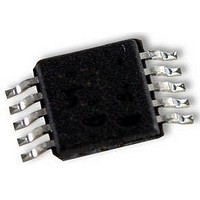
UPD78F9502MA-CAC-A NEC, UPD78F9502MA-CAC-A Datasheet - Page 211

UPD78F9502MA-CAC-A
Manufacturer Part Number
UPD78F9502MA-CAC-A
Description
8BIT MCU, 4K FLASH, 128B RAM, SMD
Manufacturer
NEC
Datasheet
1.UPD78F9502MA-CAC-A.pdf
(229 pages)
Specifications of UPD78F9502MA-CAC-A
Controller Family/series
UPD78F
No. Of I/o's
8
Ram Memory Size
128Byte
Cpu Speed
10MHz
No. Of Timers
2
No. Of Pwm
RoHS Compliant
Core Size
8bit
Program Memory Size
4KB
Oscillator Type
External, Internal
- Current page: 211 of 229
- Download datasheet (2Mb)
Cautions 1.
Note After opening the dry pack, store it at 25 C or less and 65% RH or less for the allowable storage period.
Caution Do not use different soldering methods together (except for partial heating).
Infrared reflow
Wave soldering
Partial heating
Soldering Method
These products should be soldered and mounted under the following recommended conditions.
For technical information, see the following website.
Semiconductor Device Mount Manual (http://www.necel.com/pkg/en/mount/index.html)
10-pin plastic SSOP (lead-free products)
PD78F9500MA-CAC-A, 78F9501MA-CAC-A, 78F9502MA-CAC-A
2. For soldering methods and conditions other than those recommended below, contact an NEC
Products whis –A at the end of the part number are lead-free products.
Electronics sales representative.
Package peak temperature: 260 C, Time: 30 seconds max. (at 210 C or higher),
Count: 3 times or less, Exposure limit: 7 days
10 to 72 hours)
For details, contact an NEC Electronics sales representative.
Pin temperature: 350 C max., Time: 3 seconds max. (per pin row)
CHAPTER 18 RECOMMENDED SOLDERING CONDITIONS
Table 18-1. Surface Mounting Type Soldering Conditions
Preliminary User’s Manual U18681EJ1V0UD
Soldering Conditions
Note
(after that, prebake at 125 C for
IR60-107-3
Condition Symbol
Recommended
211
Related parts for UPD78F9502MA-CAC-A
Image
Part Number
Description
Manufacturer
Datasheet
Request
R

Part Number:
Description:
16/8 bit single-chip microcomputer
Manufacturer:
NEC
Datasheet:

Part Number:
Description:
Dual audio power amp circuit
Manufacturer:
NEC
Datasheet:

Part Number:
Description:
Dual comparator
Manufacturer:
NEC
Datasheet:

Part Number:
Description:
MOS type composite field effect transistor
Manufacturer:
NEC
Datasheet:

Part Number:
Description:
50 V/100 mA FET array incorporating 2 N-ch MOSFETs
Manufacturer:
NEC
Datasheet:

Part Number:
Description:
6-pin small MM high-frequency double transistor
Manufacturer:
NEC
Datasheet:

Part Number:
Description:
6-pin small MM high-frequency double transistor
Manufacturer:
NEC
Datasheet:

Part Number:
Description:
6-pin small MM high-frequency double transistor
Manufacturer:
NEC
Datasheet:

Part Number:
Description:
6-pin small MM high-frequency double transistor
Manufacturer:
NEC
Datasheet:

Part Number:
Description:
Twin transistors equipped with different model chips(6P small MM)
Manufacturer:
NEC
Datasheet:

Part Number:
Description:
Bipolar analog integrated circuit
Manufacturer:
NEC
Datasheet:


