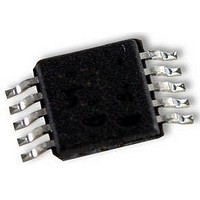
UPD78F9502MA-CAC-A NEC, UPD78F9502MA-CAC-A Datasheet - Page 98

UPD78F9502MA-CAC-A
Manufacturer Part Number
UPD78F9502MA-CAC-A
Description
8BIT MCU, 4K FLASH, 128B RAM, SMD
Manufacturer
NEC
Datasheet
1.UPD78F9502MA-CAC-A.pdf
(229 pages)
Specifications of UPD78F9502MA-CAC-A
Controller Family/series
UPD78F
No. Of I/o's
8
Ram Memory Size
128Byte
Cpu Speed
10MHz
No. Of Timers
2
No. Of Pwm
RoHS Compliant
Core Size
8bit
Program Memory Size
4KB
Oscillator Type
External, Internal
- Current page: 98 of 229
- Download datasheet (2Mb)
8.1
8.2
98
Maskable
Reset
Interrupt Type
Notes 1.
There are two types of interrupts: maskable interrupts and resets.
There are a total of 4 maskable interrupt sources, and up to four reset sources (see Table 8-1).
Interrupt Function Types
Interrupt Sources and Configuration
Maskable interrupts
These interrupts undergo mask control. When an interrupt request occurs, the standby release signal occurs,
and if an interrupt can be acknowledged then the program corresponding to the address written in the vector
table address is executed (vector interrupt servicing). When several interrupt requests are generated at the
same time, processing takes place in the priority order of the vector interrupt servicing. For details on the
priority order, see Table 8-1.
There are two internal sources and two external sources of maskable interrupts.
Reset
The CPU and SFR are returned to their initial states by the reset signal.
occurrences are shown in Table 8-1.
When a reset signal occurs, program execution starts from the programs at the addresses written in addresses
0000H and 0001H.
2. Basic configuration types (A) and (B) correspond to (A) and (B) in Figure 8-1.
3. When bit 1 (LVIMD) of low-voltage detection register (LVIM) = 0 is selected.
4. When bit 1 (LVIMD) of low-voltage detection register (LVIM) = 1 is selected.
Priority is the vector interrupt servicing priority order when several maskable interrupt requests are
generated at the same time. 1 is the highest and 4 is the lowest.
Priority
1
2
3
4
Note 1
INTLVI
INTP0
INTP1
INTTMH1
RESET
POC
LVI
WDT
Name
CHAPTER 8 INTERRUPT FUNCTIONS
Preliminary User’s Manual U18681EJ1V0UD
Low-voltage detection
Pin input edge detection
Match between TMH1 and CMP01
(when compare register is specified)
Reset input
Power-on-clear
Low-voltage detection
WDT overflow
Table 8-1. Interrupt Sources
Interrupt Source
Trigger
Note 3
Note 4
Internal
External
Internal
Internal/
External
The causes for reset signal
Vector Table
Address
000CH
0006H
0008H
000AH
0000H
Configuration
Type
Basic
(A)
(B)
(A)
Note 2
Related parts for UPD78F9502MA-CAC-A
Image
Part Number
Description
Manufacturer
Datasheet
Request
R

Part Number:
Description:
16/8 bit single-chip microcomputer
Manufacturer:
NEC
Datasheet:

Part Number:
Description:
Dual audio power amp circuit
Manufacturer:
NEC
Datasheet:

Part Number:
Description:
Dual comparator
Manufacturer:
NEC
Datasheet:

Part Number:
Description:
MOS type composite field effect transistor
Manufacturer:
NEC
Datasheet:

Part Number:
Description:
50 V/100 mA FET array incorporating 2 N-ch MOSFETs
Manufacturer:
NEC
Datasheet:

Part Number:
Description:
6-pin small MM high-frequency double transistor
Manufacturer:
NEC
Datasheet:

Part Number:
Description:
6-pin small MM high-frequency double transistor
Manufacturer:
NEC
Datasheet:

Part Number:
Description:
6-pin small MM high-frequency double transistor
Manufacturer:
NEC
Datasheet:

Part Number:
Description:
6-pin small MM high-frequency double transistor
Manufacturer:
NEC
Datasheet:

Part Number:
Description:
Twin transistors equipped with different model chips(6P small MM)
Manufacturer:
NEC
Datasheet:

Part Number:
Description:
Bipolar analog integrated circuit
Manufacturer:
NEC
Datasheet:


