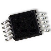
UPD78F9502MA-CAC-A NEC, UPD78F9502MA-CAC-A Datasheet - Page 38

UPD78F9502MA-CAC-A
Manufacturer Part Number
UPD78F9502MA-CAC-A
Description
8BIT MCU, 4K FLASH, 128B RAM, SMD
Manufacturer
NEC
Datasheet
1.UPD78F9502MA-CAC-A.pdf
(229 pages)
Specifications of UPD78F9502MA-CAC-A
Controller Family/series
UPD78F
No. Of I/o's
8
Ram Memory Size
128Byte
Cpu Speed
10MHz
No. Of Timers
2
No. Of Pwm
RoHS Compliant
Core Size
8bit
Program Memory Size
4KB
Oscillator Type
External, Internal
- Current page: 38 of 229
- Download datasheet (2Mb)
3.3 Instruction Address Addressing
incremented (+1 for each byte) automatically according to the number of bytes of an instruction to be fetched each
time another instruction is executed.
information is set to the PC to branch by the following addressing (for details of each instruction, refer to 78K/0S
Series Instructions User’s Manual (U11047E)).
3.3.1 Relative addressing
38
An instruction address is determined by the program counter (PC) contents. The PC contents are normally
[Function]
[Illustration]
The value obtained by adding 8-bit immediate data (displacement value: jdisp8) of an instruction code to the start
address of the following instruction is transferred to the program counter (PC) to branch. The displacement
value is treated as signed two’s complement data (–128 to +127) and bit 7 becomes the sign bit. In other words,
the range of branch in relative addressing is between –128 and +127 of the start address of the following
instruction.
This function is carried out when the BR $addr16 instruction or a conditional branch instruction is executed.
PC
15
15
15
When S = 0,
When S = 1,
indicates that all bits are “0”.
indicates that all bits are “1”.
Preliminary User’s Manual U18681EJ1V0UD
When a branch instruction is executed, the branch destination address
CHAPTER 3 CPU ARCHITECTURE
8
PC
+
7
S
6
jdisp8
0
0
0
... PC is the start address of
the next instruction of
a BR instruction.
Related parts for UPD78F9502MA-CAC-A
Image
Part Number
Description
Manufacturer
Datasheet
Request
R

Part Number:
Description:
16/8 bit single-chip microcomputer
Manufacturer:
NEC
Datasheet:

Part Number:
Description:
Dual audio power amp circuit
Manufacturer:
NEC
Datasheet:

Part Number:
Description:
Dual comparator
Manufacturer:
NEC
Datasheet:

Part Number:
Description:
MOS type composite field effect transistor
Manufacturer:
NEC
Datasheet:

Part Number:
Description:
50 V/100 mA FET array incorporating 2 N-ch MOSFETs
Manufacturer:
NEC
Datasheet:

Part Number:
Description:
6-pin small MM high-frequency double transistor
Manufacturer:
NEC
Datasheet:

Part Number:
Description:
6-pin small MM high-frequency double transistor
Manufacturer:
NEC
Datasheet:

Part Number:
Description:
6-pin small MM high-frequency double transistor
Manufacturer:
NEC
Datasheet:

Part Number:
Description:
6-pin small MM high-frequency double transistor
Manufacturer:
NEC
Datasheet:

Part Number:
Description:
Twin transistors equipped with different model chips(6P small MM)
Manufacturer:
NEC
Datasheet:

Part Number:
Description:
Bipolar analog integrated circuit
Manufacturer:
NEC
Datasheet:


