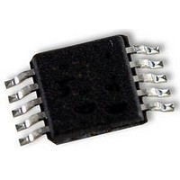
UPD78F9502MA-CAC-A NEC, UPD78F9502MA-CAC-A Datasheet - Page 224

UPD78F9502MA-CAC-A
Manufacturer Part Number
UPD78F9502MA-CAC-A
Description
8BIT MCU, 4K FLASH, 128B RAM, SMD
Manufacturer
NEC
Datasheet
1.UPD78F9502MA-CAC-A.pdf
(229 pages)
Specifications of UPD78F9502MA-CAC-A
Controller Family/series
UPD78F
No. Of I/o's
8
Ram Memory Size
128Byte
Cpu Speed
10MHz
No. Of Timers
2
No. Of Pwm
RoHS Compliant
Core Size
8bit
Program Memory Size
4KB
Oscillator Type
External, Internal
- Current page: 224 of 229
- Download datasheet (2Mb)
224
Interrupt
functions
Standby
Function
Reset
function
Function
IF0: Interrupt
request flag
registers,
MK0: Interrupt
mask flag
registers
INTM0: External
interrupt mode
register 0
Interrupt
requests are
held pending
Interrupt
request pending
STOP mode
STOP mode
HALT mode
setting and
operating
statuses
STOP mode
setting and
operating
statuses
Timing of reset
by overflow of
watchdog timer
RESF: Reset
control flag
register
Details of
Function
Because P21 and P32 have an alternate function as external interrupt inputs,
when the output level is changed by specifying the output mode of the port
function, an interrupt request flag is set. Therefore, the interrupt mask flag should
be set to 1 before using the output mode.
Be sure to clear bits 0, 1, 6, and 7 to 0.
Before setting the INTM0 register, be sure to set the corresponding interrupt mask
flag (
interrupt request flag (
which will enable interrupts.
Interrupt requests will be held pending while the interrupt request flag registers
(IF0) or interrupt mask flag registers (MK0) are being accessed.
Multiple interrupts can be acknowledged even for low-priority interrupts.
The LSRSTOP setting is valid only when “Can be stopped by software” is set for
the low-speed internal oscillator by the option byte.
When shifting to the STOP mode, be sure to stop the peripheral hardware
operation before executing STOP instruction (except the peripheral hardware that
operates on the low-speed internal oscillation clock).
If the low-speed internal oscillator is operating before the STOP mode is set,
oscillation of the low-speed internal oscillation clock cannot be stopped in the
STOP mode (refer to Table 9-1).
Because an interrupt request signal is used to clear the standby mode, if there is
an interrupt source with the interrupt request flag set and the interrupt mask flag
clear, the standby mode is immediately cleared if set.
Because an interrupt request signal is used to clear the standby mode, if there is
an interrupt source with the interrupt request flag set and the interrupt mask flag
reset, the standby mode is immediately cleared if set. Thus, in the STOP mode,
the normal operation mode is restored after the STOP instruction is executed and
then the operation is stopped for 34 s (TYP.).
For an external reset, input a low level for 2 s or more to the RESET pin.
During reset signal generation, the system clock and low-speed internal oscillation
clock stop oscillating.
When the RESET pin is used as an input-only port pin (P34), the PD78F9500,
78F9501, 78F9502 is reset if a low level is input to the RESET pin after reset is
released by the POC circuit and before the option byte is referenced again. The
reset status is retained until a high level is input to the RESET pin.
The LVI circuit is not reset by the internal reset signal of the LVI circuit.
The watchdog timer is also reset in the case of an internal reset of the watchdog
timer.
Do not read data by a 1-bit memory manipulation instruction.
MK = 1) to disable interrupts. After setting the INTM0 register, clear the
Preliminary User’s Manual U18681EJ1V0UD
APPENDIX C LIST OF CAUTIONS
IF = 0), then clear the interrupt mask flag (
Cautions
MK = 0),
pp. 100,
101
p. 101
p. 102
p. 104
p. 105
p. 107
p. 108
p. 108
p. 109
p. 111
p. 114
p. 114
p. 114
p. 115
p. 116
p. 118
Page
(3/7)
Related parts for UPD78F9502MA-CAC-A
Image
Part Number
Description
Manufacturer
Datasheet
Request
R

Part Number:
Description:
16/8 bit single-chip microcomputer
Manufacturer:
NEC
Datasheet:

Part Number:
Description:
Dual audio power amp circuit
Manufacturer:
NEC
Datasheet:

Part Number:
Description:
Dual comparator
Manufacturer:
NEC
Datasheet:

Part Number:
Description:
MOS type composite field effect transistor
Manufacturer:
NEC
Datasheet:

Part Number:
Description:
50 V/100 mA FET array incorporating 2 N-ch MOSFETs
Manufacturer:
NEC
Datasheet:

Part Number:
Description:
6-pin small MM high-frequency double transistor
Manufacturer:
NEC
Datasheet:

Part Number:
Description:
6-pin small MM high-frequency double transistor
Manufacturer:
NEC
Datasheet:

Part Number:
Description:
6-pin small MM high-frequency double transistor
Manufacturer:
NEC
Datasheet:

Part Number:
Description:
6-pin small MM high-frequency double transistor
Manufacturer:
NEC
Datasheet:

Part Number:
Description:
Twin transistors equipped with different model chips(6P small MM)
Manufacturer:
NEC
Datasheet:

Part Number:
Description:
Bipolar analog integrated circuit
Manufacturer:
NEC
Datasheet:


