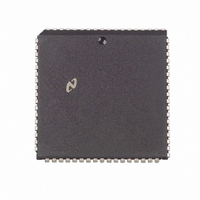
NS32FX164AV-25 National Semiconductor, NS32FX164AV-25 Datasheet - Page 12

NS32FX164AV-25
Manufacturer Part Number
NS32FX164AV-25
Description
IC IMAGING COMM SGNL PROC PLCC68
Manufacturer
National Semiconductor
Datasheet
1.NS32FX164AV-25.pdf
(102 pages)
Specifications of NS32FX164AV-25
Processor Type
Advanced Imaging/Communications Signal Processor SIAP™
Speed
50MHz
Voltage
5V
Mounting Type
Surface Mount
Package / Case
68-PLCC
Lead Free Status / RoHS Status
Contains lead / RoHS non-compliant
Features
-
Other names
*NS32FX164AV-25
Q1284286
Q1284286
Available stocks
Company
Part Number
Manufacturer
Quantity
Price
Company:
Part Number:
NS32FX164AV-25
Manufacturer:
NSC
Quantity:
12 388
Company:
Part Number:
NS32FX164AV-25
Manufacturer:
Texas Instruments
Quantity:
10 000
2 0 Architectural Description
Although memory is addressed as bytes it is actually orga-
nized as words Therefore words and double-words that are
aligned to start at even addresses (multiples of two) are
accessed more quickly than words and double-words that
are not so aligned
2 2 1 Address Mapping
The NS32FX164 supports the use of memory-mapped pe-
ripheral devices and coprocessors Such memory-mapped
devices can be located at arbitrary locations within the
16-Mbyte address range available externally
Addresses marked as Reserved in Figure 2-15 are not avail-
able in the present implementation of the NS32FX164 and
should not be used The top 8-Mbyte block is reserved by
National Semiconductor Corporation and only a few loca-
tions within this block are presently used to access the on-
chip RAM array and DSP Module registers Figure 2-15
shows the NS32FX164 address mapping
2 3 MODULAR SOFTWARE SUPPORT
The NS32FX164 provides special support for software mod-
ules and modular programs
Each module in a NS32FX164 software environment con-
sists of three components
1 Program Code Segment
2 Static Data Segment
3 Link Table
This segment contains the module’s code and constant
data
Used to store variables and data that may be accessed
by all procedures within the module
This component contains two types of entries Absolute
Addresses and Procedure Descriptors
An Absolute Address is used in the external addressing
mode in conjunction with a displacement and the current
MOD Register contents to compute the effective address
of an external variable belonging to another module
The Procedure Descriptor is used in the call external pro-
cedure (CXP) instruction to compute the address of an
external procedure
Start Address
00FFFE00
FFFE0000
FFFE1000
FFFF8000
FFFF8028
FFFF9000
FFFF9014
00000000
01000000
FIGURE 2-15 NS32FX164 Address Mapping
(HEX)
Memory and I O
Interrupt Control
Reserved
DSPM Internal RAM
Reserved
DSPM Dedicated Registers
Reserved
DSPM Control Status Registers
Reserved
(Continued)
12
Figure 2-17 shows the general format of a Series 32000
Normally the linker program specifies the locations of the
three components The Static Data and Link Table typically
reside in RAM the code component can be either in RAM or
in ROM The three components can be mapped into non-
contiguous locations in memory and each can be indepen-
dently relocated Since the Link Table contains the absolute
addresses of external variables the linker need not assign
absolute memory addresses for these in the module itself
they may be assigned at load time
To handle the transfer of control from one module to anoth-
er the NS32FX164 uses a module table in memory and two
registers in the CPU
The Module Table is located within the first 64 kbytes of
memory This table contains a Module Descriptor (also
called a Module Table Entry) for each module in the ad-
dress space of the program A Module Descriptor has four
32-bit entries corresponding to each component of a mod-
ule
The MOD Register in the CPU contains the address of the
Module Descriptor for the currently executing module
The Static Base Register (SB) contains a copy of the Static
Base entry in the Module Descriptor of the currently execut-
ing module i e it points to the beginning of the current
module’s static data area
This register is implemented in the CPU for efficiency pur-
poses By having a copy of the static base entry or chip the
CPU can avoid reading it from memory each time a data
item in the static data segment is accessed
In an NS32FX164 software environment modules need not
be linked together prior to loading As modules are loaded
a linking loader simply updates the Module Table and fills
the Link Table entries with the appropriate values No modi-
fication of a module’s code is required Thus modules may
be stored in read-only memory and may be added to a sys-
tem independently of each other without regard to their in-
dividual
NS32FX164 run-time environment
2 4 INSTRUCTION SET
2 4 1 General Instruction Format
instruction The Basic Instruction is one to three bytes long
and contains the Opcode and up to two 5-bit General Ad-
dressing Mode (‘‘Gen’’) fields Following the Basic Instruc-
tion field is a set of optional extensions which may appear
depending on the instruction and the addressing modes se-
lected
Index Bytes appear when either or both Gen fields specify
Scaled Index In this case the Gen field specifies only the
Scale Factor (1 2 4 or 8) and the Index Byte specifies
which General Purpose Register to use as the index and
which addressing mode calculation to perform before index-
ing
The Static Base entry contains the address of the begin-
ning of the module’s static data segment
The Link Table Base points to the beginning of the mod-
ule’s Link Table
The Program Base is the address of the beginning of the
code and constant data for the module
A fourth entry is currently unused but reserved
addressing
Figure
2-16
shows
a
typical


