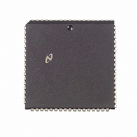
NS32FX164AV-25 National Semiconductor, NS32FX164AV-25 Datasheet - Page 4

NS32FX164AV-25
Manufacturer Part Number
NS32FX164AV-25
Description
IC IMAGING COMM SGNL PROC PLCC68
Manufacturer
National Semiconductor
Datasheet
1.NS32FX164AV-25.pdf
(102 pages)
Specifications of NS32FX164AV-25
Processor Type
Advanced Imaging/Communications Signal Processor SIAP™
Speed
50MHz
Voltage
5V
Mounting Type
Surface Mount
Package / Case
68-PLCC
Lead Free Status / RoHS Status
Contains lead / RoHS non-compliant
Features
-
Other names
*NS32FX164AV-25
Q1284286
Q1284286
Available stocks
Company
Part Number
Manufacturer
Quantity
Price
Company:
Part Number:
NS32FX164AV-25
Manufacturer:
NSC
Quantity:
12 388
Company:
Part Number:
NS32FX164AV-25
Manufacturer:
Texas Instruments
Quantity:
10 000
FIGURE 2-27 TBITS Instruction Format
FIGURE 2-28 SBITS Instruction Format
FIGURE 2-29 SBITPS Instruction Format
FIGURE 2-30 Bus Activity for a Simple BITBLT Operation
FIGURE 3-1
FIGURE 3-2
FIGURE 3-3
FIGURE 3-4
FIGURE 3-5
FIGURE 3-6
FIGURE 3-7
FIGURE 3-8
FIGURE 3-9
FIGURE 3-10 Cascaded Interrupt Control Unit Connections
FIGURE 3-11 Exception Processing Flowchart
FIGURE 3-12 Service Sequence
FIGURE 3-13 DSP Module Block Diagram
FIGURE 3-14 Power and Ground Connections
FIGURE 3-15 Crystal Interconnections 30 MHz
FIGURE 3-16 Crystal Interconnections 40 MHz 50 MHz
FIGURE 3-17 Recommended Reset Connections
FIGURE 3-18 Power-On Reset Requirements
FIGURE 3-19 General Reset Timing
FIGURE 3-20 Bus Connections
FIGURE 3-21 Read Cycle Timing
FIGURE 3-22 Write Cycle Timing
FIGURE 3-23 Cycle Extension of a Read Cycle
FIGURE 3-24 Special Bus Cycle Timing
FIGURE 3-25 Slave Processor Read Cycle
FIGURE 3-26 Slave Processor Write Cycle
FIGURE 3-27 NS32FX164 and FPU Interconnections
FIGURE 3-28 Memory Interface
FIGURE 3-29 HOLD Timing (Bus Initially Idle)
FIGURE 3-30 HOLD Timing (Bus Initially Not Idle)
FIGURE 4-1
FIGURE 4-2
FIGURE 4-3a Input Signals Specification Standard
FIGURE 4-3b RSTI INT NMI Hysteresis
FIGURE 4-4
FIGURE 4-5
FIGURE 4-6
FIGURE 4-7
FIGURE 4-8
FIGURE 4-9
FIGURE 4-10 Slave Processor Write Timing
FIGURE 4-11 Slave Processor Read Timing
FIGURE 4-12 SPC Timing
FIGURE 4-13 PFS Signal Timing
FIGURE 4-14 ILO Signal Timing
FIGURE 4-15 Clock Waveforms
FIGURE 4-16 INT Signal Timing
Operating States
Slave Processor Protocol
Slave Processor Status Word
Interrupt Dispatch and Cascade Tables
Exception Acknowledge Sequence Direct-Exception Mode Disabled
Exception Acknowledge Sequence Direct-Exception Mode Enabled
Return from Trap (RETTn) Instruction Flow Direct-Exception Mode Disabled
Return from Interrupt (RETI) Instruction Flow Direct-Exception Mode Disabled
Interrupt Control Unit Connections (16 Levels)
Connection Diagram
Output Signals Specification Standard
Read Cycle
Write Cycle
Special Bus Cycle
HOLD Acknowledge Timing (Bus Initially Not Idle)
HOLD Timing (Bus Initially Idle)
External DMA Controller Bus Cycle
List of Figures
4
(Continued)
24
25
25
25
26
28
29
30
31
32
33
34
35
36
38
39
55
56
56
56
56
57
57
59
60
61
63
65
66
67
67
67
69
70
73
74
74
74
79
80
81
82
83
84
85
85
85
86
86
86
87


