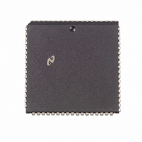
NS32FX164AV-25 National Semiconductor, NS32FX164AV-25 Datasheet - Page 77

NS32FX164AV-25
Manufacturer Part Number
NS32FX164AV-25
Description
IC IMAGING COMM SGNL PROC PLCC68
Manufacturer
National Semiconductor
Datasheet
1.NS32FX164AV-25.pdf
(102 pages)
Specifications of NS32FX164AV-25
Processor Type
Advanced Imaging/Communications Signal Processor SIAP™
Speed
50MHz
Voltage
5V
Mounting Type
Surface Mount
Package / Case
68-PLCC
Lead Free Status / RoHS Status
Contains lead / RoHS non-compliant
Features
-
Other names
*NS32FX164AV-25
Q1284286
Q1284286
Available stocks
Company
Part Number
Manufacturer
Quantity
Price
Company:
Part Number:
NS32FX164AV-25
Manufacturer:
NSC
Quantity:
12 388
Company:
Part Number:
NS32FX164AV-25
Manufacturer:
Texas Instruments
Quantity:
10 000
Symbol Figure
t
t
t
t
t
t
t
t
t
t
t
t
t
t
t
t
t
t
t
t
Symbol
IASa
IASia
IASw
AIASs
ILOa
ILOia
RSTOa
RSTOia
RTOI
IOUTv
IOUTh
Xp
Xh
XI
DIs
DIh
CWs
CWh
HLDs
HLDh
4 0 Device Specifications
4 4 2 Timing Tables (Continued)
4 4 2 1 Output Signals Internal Propagation Delays NS32FX161-15 NS32FX164-20 NS32FX164-25
Note 1 Every memory cycle starts with T4 during which Cycle Status is applied If the CPU was idling the sequence will be ‘‘
Note 2 The parameters related to the ‘‘floating not floating’’ conditions are guaranteed by characterization Due to tester conditions these parameters are not
Note 3 Not tested guaranteed by design
Note 4 Minimum values not tested guaranteed by design
Note 5 When the load on AD0–15 is increased to 90 pF the value of t
4 4 2 2 Input Signal Requirements NS32FX164-15 NS32FX164-20 and NS32FX164-25
not idling the sequence will be ‘‘
100% tested
value of t
4-4 4-11 Data In Setup
4-4 4-11 Data In Hold
4-14
4-14
4-19
4-19
4-19
4-20
4-20
4-4 4-5
4-4 4-5
4-7 4-8
4-7 4-8
4-6
4-6
4-6
4-6
Figure
4-15
4-15
4-15
AHv
IAS Signal Active
IAS Signal Inactive
(Note 4)
IAS Pulse Width
AD0–AD15 Setup
ILO Signal Active
ILO Signal Inactive
RSTO Signal Active
RSTO Signal Inactive After R E CTTL
Reset to Idle
(Note 3)
IOUT Signal Valid
IOUT Signal Hold
is increased by no more than 5 ns
OSCIN Clock Period R E OSCIN
OSCIN High Time
(External Clock)
OSCIN Low Time
(Note 1)
CWAIT Signal Setup Before R E CTTL
CWAIT Signal Hold
HOLD Setup Time
HOLD Hold Time
Description
Description
T4 T1
After R E CTTL T1
After R E CTTL T1
At 0 8V (Both Edges)
Before IAS T E
After R E CTTL
After R E CTTL
After R E CTTL
After F E of RSTO
After R E CTTL
After R E CTTL
to Next R E OSCIN
At 3 5V (Both Edges)
At 1 0V (Both Edges)
Before R E CTTL T4
After R E CTTL T4
T3 or T3(w)
After R E CTTL
T3 or T3(w)
Before R E CTTL
T2 or Ti
After R E CTTL Ti
(Continued)
Reference
Conditions
’’
Reference
Conditions
ALv
is increased by no more than 5 ns When the load on A16–23 is increased to 90 pF the
0 5 t
77
b
NS32FX161-15
Min
20
10
6 ns
0
b
b
0 5 t
0 5 t
CTp
NS32FX164-15
Min
33
15
18
16
5 ns
5 ns
0
0
0
Xp
Xp
0 5 t
a
Max
16 ns
14
14
14
14
14
10
14
CTp
Max
500
0 5 t
b
NS32FX164-20
Min
0 5 t
b
0 5 t
b
15
10
6 ns
NS32FX164-20
0
Min
CTp
25
14
13
15
4 ns
4 ns
0
0
0
Xp
Xp
0 5 t
a
Max
15 ns
13
13
13
13
13
10
13
Max
500
CTp
Ti T4 T1
0 5 t
b
b
b
0 5 t
0 5 t
NS32FX164-25
NS32FX164-25
Min
10
10
Min
6 ns
20
10
14
0
10
3 ns
3 ns
0
0
0
CTp
Xp
Xp
’’ If the CPU was
0 5 t
a
Max
Max
500
14 ns
12
12
12
12
12
10
12
CTp
Units
Units
t
ns
ns
ns
ns
ns
ns
ns
CTp
ns
ns
ns
ns
ns
ns
ns
ns
ns


