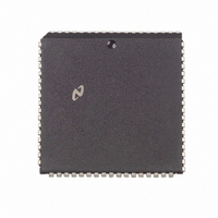
NS32FX164AV-25 National Semiconductor, NS32FX164AV-25 Datasheet - Page 42

NS32FX164AV-25
Manufacturer Part Number
NS32FX164AV-25
Description
IC IMAGING COMM SGNL PROC PLCC68
Manufacturer
National Semiconductor
Datasheet
1.NS32FX164AV-25.pdf
(102 pages)
Specifications of NS32FX164AV-25
Processor Type
Advanced Imaging/Communications Signal Processor SIAP™
Speed
50MHz
Voltage
5V
Mounting Type
Surface Mount
Package / Case
68-PLCC
Lead Free Status / RoHS Status
Contains lead / RoHS non-compliant
Features
-
Other names
*NS32FX164AV-25
Q1284286
Q1284286
Available stocks
Company
Part Number
Manufacturer
Quantity
Price
Company:
Part Number:
NS32FX164AV-25
Manufacturer:
NSC
Quantity:
12 388
Company:
Part Number:
NS32FX164AV-25
Manufacturer:
Texas Instruments
Quantity:
10 000
3 0 Functional Description
accumulator Bit 0 of the extended-precision argument is
not used during calculations This bit is always set to ‘‘0’’
when stored back in the internal memory
Extended-precision real values are used to represent vari-
ous continuous quantities that require high accuracy The
range of extended-precision real values is from
sented as 0x80000000) through 1 0
as 0x7FFFFFFE)
3 4 2 6 Complex Values
Complex values are represented as pairs of real values and
must be aligned on a double-word boundary The less signif-
icant half represents the real part and must be contained in
an even-numbered memory location The more significant
half represents the imaginary part and must be contained in
the next (odd-numbered) memory location
Complex values are used to represent samples of complex
baseband signals constellation points in the complex plane
coefficients of complex filters and rotation angles as points
on the unit circle etc Both the real and imaginary parts
have the same range and accuracy as specified for real
values above
3 4 3 Command List Format
All commands have the same fixed format consisting of a
5-bit opcode field and a 11-bit arg field as shown below
The opcode field specifies an operation to be performed
The arg field interpretation is determined by the class to
which the command belongs There are several classes of
commands as follows
See Section 3 4 5 for detailed information on the DSPM in-
struction set
3 4 4 CPU Core Interface
The interface between the DSPM and the CPU core con-
sists of the following elements
15
15
15
Load Register Instructions
Store Register Instructions
Adjust Register Instructions
Flow Control Instructions
Internal Memory Move Instructions
External Memory Move Instructions
Arithmetic Logical Instructions
Multiply-and-Accumulate Instructions
Multiply-and-Add Instructions
Clipping and Min Max Instructions
Special Instructions
Parallel Operation and Synchronization
CPU Core Address Space Map
External Memory References
More Significant Part
Less Significant Part
opcode
Imaginary Part
Real Part
11 10
0
0
(Location 2 n )
(Location 2 n
(Location 2 n )
(Location 2 n
arg
b
2
b
30
a
a
(Continued)
(represented
1)
b
1)
1 0 (repre-
0
42
3 4 4 1 Synchronization of Parallel Operation
Since the DSPM is capable of autonomous operation paral-
lel to the CPU core operation a mechanism is needed to
synchronize the two threads of execution The parallel syn-
chronization mechanism consists of several control and
status registers which are used to synchronize the following
activities
The following CPU core interface control and status regis-
ters are available
Execution of the command list begins when the CPU core
writes a value into the CLPTR control register This causes
the DSPM command-list execution unit to begin executing
commands starting at the address written to the CLPTR
register If the written value is outside the range of valid
RAM addresses the result is unpredictable
Once started execution of the command list continues until
one of the following occurs a HALT or a DBPT command is
executed the CPU core writes any value into the ABORT
control register an attempt to execute a reserved com-
mand an attempt to access the DSPM address space while
the CLSTAT RUN bit is ‘‘1’’ (except for accesses to the
CLSTAT EXT DSPINT DSPMASK NMISTAT and ABORT
registers) or reset occurs In the last case the contents of
the DSPM internal RAM REPEAT and CLPTR registers are
unpredictable when execution terminates
The CLSTAT status register can be read by CPU core in-
structions to check whether execution of the DSPM com-
mand list is active or idle A ‘‘0’’ value read from the
CLSTAT RUN bit indicates that execution is idle and a ‘‘1’’
value indicates that it is active
Whenever the execution of the command list terminates
CLSTAT RUN changes its value from ‘‘1’’ to ‘‘0’’ and
DSPINT HALT is set to ‘‘1’’ The value of the DSPINT HALT
status bit can be used to generate interrupts
DSPMASK HALT is set a ‘‘1’’ value on the DSPINT HALT
will cause the IOUT output signal to become active (low)
IOUT can be connected to an external Interrupt Controller
Unit (ICU) or directly to the INT input of the NS32FX164
The DSPM internal RAM and the dedicated registers as
well as the interface control and status registers are
mapped into certain areas of the CPU core address space
(see Section 2 2 1) Whenever execution of the DSPM com-
mand list is idle CPU core instructions may access these
CLPTR
CLSTAT
ABORT
EXT
DSPINT
DSPMASK
NMISTAT
Initiation of the command list execution
Termination of the command list execution
Check the DSPM status
Access to DSPM internal RAM and registers by CPU
core instructions
Access to external memory by DSPM commands
Register
Command-List Pointer
Command-List Status Register
Abort Register
Disable External Memory References
Interrupt Register
Mask Register
NMI Status Register
Function
If


