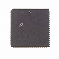
NS32FX164AV-25 National Semiconductor, NS32FX164AV-25 Datasheet - Page 39

NS32FX164AV-25
Manufacturer Part Number
NS32FX164AV-25
Description
IC IMAGING COMM SGNL PROC PLCC68
Manufacturer
National Semiconductor
Datasheet
1.NS32FX164AV-25.pdf
(102 pages)
Specifications of NS32FX164AV-25
Processor Type
Advanced Imaging/Communications Signal Processor SIAP™
Speed
50MHz
Voltage
5V
Mounting Type
Surface Mount
Package / Case
68-PLCC
Lead Free Status / RoHS Status
Contains lead / RoHS non-compliant
Features
-
Other names
*NS32FX164AV-25
Q1284286
Q1284286
Available stocks
Company
Part Number
Manufacturer
Quantity
Price
Company:
Part Number:
NS32FX164AV-25
Manufacturer:
NSC
Quantity:
12 388
Company:
Part Number:
NS32FX164AV-25
Manufacturer:
Texas Instruments
Quantity:
10 000
3 0 Functional Description
3 2 7 Exception Acknowledge Sequences
Detailed Flow
For purposes of the following detailed discussion of excep-
tion acknowledge sequences a single sequence called
‘‘service’’ is defined in Figure 3-12
Upon detecting any interrupt request or trap condition the
CPU first performs a sequence dependent upon the type of
exception This sequence will include saving a copy of the
Processor Status Register and establishing a vector and a
return address The CPU then performs the service se-
quence
3 2 7 1 Maskable Non-Maskable Interrupt Sequence
This sequence is performed by the CPU when the NMI pin
receives a falling edge or the INT pin becomes active with
the PSR I bit set The interrupt sequence begins either at
the next instruction boundary or in the case of the String
instructions or Graphics instructions which have interior
loops (BBOR BBXOR BBAND BBFOR EXTBLT MOVMP
SBITPS TBITS) at the next interruptible point during its ex-
ecution The graphics instructions are interruptible
1 If a String instruction was interrupted and not yet com-
2 Copy the Processor Status Register (PSR) into a tempo-
3 If the interrupt is Non-Maskable
4 If the interrupt is Non-Vectored
5 Here the interrupt is Vectored Read ‘‘Byte’’ from ad-
6 If ‘‘Byte’’
7 If ‘‘Byte’’ is in the range
8 Perform Service (Vector Return Address) Figure 3-12
3 2 7 2 SLAVE ILL SVC DVZ FLG BPT UND
Trap Sequence
1 Restore the currently selected Stack Pointer and the
pleted
a Clear the Processor Status Register P bit
b Set ‘‘Return Address’’ to the address of the first byte
Otherwise set ‘‘Return Address’’ to the address of the
next instruction
rary register then clear PSR bits S U T P and I
a Read a byte from address FFFF00
b Set ‘‘Vector’’ to 1
c Go to Step 8
a Read a byte from address FFFE00
b Set ‘‘Vector’’ to 0
c Go to Step 8
dress FFFE00
Step 8
rupt source is Cascaded (More negative values are re-
served for future use ) Perform the following
a Read the 32-bit Cascade Address from memory The
b Read ‘‘Vector’’ applying the Cascade Address just
Processor Status Register to their original values at the
start of the trapped instruction
of the interrupted instruction
Code 0100 (Interrupt Acknowledge Master Section
3 4 1) Discard the byte read
Code 0100 Discard the byte read
address is calculated as INTBASE
read and Status Code 0101
t
0 then set ‘‘Vector’’ to ‘‘Byte’’ and go to
16
applying Status Code 0100
b
16 through
16
16
b
a
1 then the inter-
applying Status
applying Status
(Continued)
4 Byte
39
2 Set ‘‘Vector’’ to the value corresponding to the trap type
3 If Trap (UND)
4 Copy the Processor Status Register (PSR) into a tempo-
5 Set ‘‘Return Address’’ to the address of the first byte of
6 Perform Service (Vector Return Address) Figure 3-12
3 2 7 3 Trace Trap Sequence
1 In the Processor Status Register (PSR) clear the P bit
2 Copy the PSR into a temporary register then clear PSR
3 Set ‘‘Vector’’ to 9
4 Set ‘‘Return Address’’ to the address of the next instruc-
5 Perform Service (Vector Return Address) Figure 3-12
Service (Vector Return Address)
10 Place IDT entry in the Program Counter
11 Push the Return Address onto the Interrupt
12 Flush queue Non-sequentially fetch first in-
SLAVE
ILL
SVC
DVZ
FLG
BPT
UND
a Clear the Processor Status Register P Bit
rary register then clear PSR bits T U S and P
the trapped instruction
bits S U and T
tion
1 Push the PSR copy onto the Interrupt Stack as a
2 Read 32-bit Interrupt Dispatch Table (IDT) entry
3 If Direct-Exception mode is selected then go to
4 Move the LS word of the IDT entry (Module
5 Read the Program Base pointer from memory
6 Read the new Static Base pointer from the
7 Push MOD Register into the Interrupt Stack as a
8 Copy temporary MOD Register into MOD Regis-
9 Go to Step 11
Stack as a 32-bit quantity
struction of Exception Service Routine
16-bit value
at address ‘‘INTBASE
Step 10
Field) into the temporary MOD register
address ‘‘MOD
of the IDT entry (Offset Field) placing the result
in the Program Counter
memory address contained in MOD placing it
into the SB Register
16-bit value
ter
Invoked during All Interrupt Trap Sequences
Vector
Vector
Vector
Vector
Vector
Vector
Vector
FIGURE 3-12 Service Sequence
e
e
e
e
e
e
e
a
3
4
5
6
7
8
10
8’’ and add to it the M S word
a
vector
c
4’’


