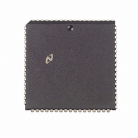
NS32FX164AV-25 National Semiconductor, NS32FX164AV-25 Datasheet - Page 99

NS32FX164AV-25
Manufacturer Part Number
NS32FX164AV-25
Description
IC IMAGING COMM SGNL PROC PLCC68
Manufacturer
National Semiconductor
Datasheet
1.NS32FX164AV-25.pdf
(102 pages)
Specifications of NS32FX164AV-25
Processor Type
Advanced Imaging/Communications Signal Processor SIAP™
Speed
50MHz
Voltage
5V
Mounting Type
Surface Mount
Package / Case
68-PLCC
Lead Free Status / RoHS Status
Contains lead / RoHS non-compliant
Features
-
Other names
*NS32FX164AV-25
Q1284286
Q1284286
Available stocks
Company
Part Number
Manufacturer
Quantity
Price
Company:
Part Number:
NS32FX164AV-25
Manufacturer:
NSC
Quantity:
12 388
Company:
Part Number:
NS32FX164AV-25
Manufacturer:
Texas Instruments
Quantity:
10 000
Appendix B Instruction Execution Times
B 2 SPECIAL GRAPHICS INSTRUCTIONS
This section provides the execution times for the special
graphics instructions Table B-3 lists the average instruction
execution times for different shift values and for a no-wait-
state system design The ‘‘No Option’’ of each instruction is
used The effect of wait states on the execution time is rath-
er difficult to evaluate due to the pipelined nature of the read
and write operations
Instructions that have shift amounts such as BBOR
BBXOR BBAND BBFOR and BITWT make use of the par-
allel nature of the Series 32000
the actual shift during the reading of the double-word desti-
nation data This means that if there are wait states on read
operations these instructions are able to shift further with-
out impacting the overall execution time For example the
total execution time for a BBFOR operation shifting 8 bits
with 2 wait states on read operations is the same as for a
BBFOR operation shifting by 12 bits This is because a des-
tination read takes 4 clock cycles longer than a no-wait-
state double-word read does Note that this effect is not
valid for more than 4 wait states because at 4 wait states all
possible shift values (0–15) are ‘‘hidden’’ during the desti-
nation read
Table B-4 shows the average execution times with wait
states assuming a shift value of eight unless stated other-
wise The parameters used in the execution time equations
are defined below
Twaitrd
Twaitr
Twaitrds The number of wait states applied for a Read
Instruction
BBOR
BBXOR
BBAND
BBFOR
BBSTOD
The number of wait states applied for a Read
operation
The number of wait states applied for a Write op-
eration
operation on source data This also refers to the
number of wait states applied for a table memory
access (in the SBITS instruction for example)
TABLE B-3 Average Instruction Execution Times with No Wait-States
EP processors by doing
42
42
44
44
45
45
48
48
48
((shift
66
66
a
a
a
a
((shift
((shift
((shift
((shift
a
a
a
a
a
a
a
a
a
a
a
(107
(107
(107
(107
(111
(111
(61
(74
(74
(170
(170
b
Number of Clock Cycles
8) width height )
b
b
b
b
a
a
a
a
a
a
a
a
a
a
a
8) width height )
8) width height )
8) width height )
8) width height )
25 ( width
32 ( width
32 ( width
44 ( width
44 ( width
44 ( width
44 ( width
44 ( width
44 ( width
60 ( width
60 ( width
99
b
b
b
b
b
b
b
b
b
b
b
Twaitrdd The number of wait states applied for a Read
Twaitwrd The number of wait states applied for a Write op-
Twaitbt
width
height
shift
B 2 1 Execution Time Calculation for Special Graphics
Instructions
The execution time for a special graphics instruction is ob-
tained by inserting the appropriate parameters to the equa-
tion for that instruction and evaluating it
For example to calculate the execution time of the BBOR
instruction applied to a 10-word wide and 5-line high data
block assuming a shift count of 15 and a no-wait-state sys-
tem the following equation from Table B-3 is used
Substituting the appropriate values to the shift width and
height parameters yields
or
This represents the ‘‘worst case’’ time for this instruction
since a shift of greater than 15 bits can be handled by mov-
ing the source and destination pointers by 2 bytes and ad-
justing the shift amount
The ‘‘best case’’ and ‘‘average case’’ times for most in-
structions are the same due to reading the destination data
during the shifting of the source data
2)) height
2)) height
2)) height
width
2)) height
2)) height
2)) height
2)) height
2)) height
2)) height
2)) height
2)) height
(Continued)
42
45
42
1 77 ms
a
a
a
(107
(107
(107
height)
operation on destination data
eration on destination data
Twaitrds
value used for BITBLT timing
The width of a BITBLT operation in words
The height of a BITBLT operation in scan lines
The number of bits of shift applied
a
a
a
15 MHz
a
44 (width
44
352)
a
(10
Twaitrdd
50
b
a
b
2))
(7
2)) height
50
500)
2
Shift
Shift
Shift
Shift
Shift
Shift
Shift
Shift
Shift
Shift
Shift
a
a
((15
e
Notes
e
l
e
l
e
l
e
e
l
e
l
Twaitwrd
a
26 492 clocks or
8
8
8
8
8
0
0
0
0
1
0
b
((shift
8)
8
8
8
8
8
b
10
2 the
8)
50)


