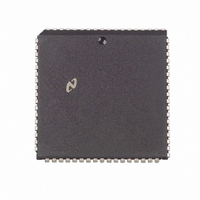
NS32FX164AV-25 National Semiconductor, NS32FX164AV-25 Datasheet - Page 56

NS32FX164AV-25
Manufacturer Part Number
NS32FX164AV-25
Description
IC IMAGING COMM SGNL PROC PLCC68
Manufacturer
National Semiconductor
Datasheet
1.NS32FX164AV-25.pdf
(102 pages)
Specifications of NS32FX164AV-25
Processor Type
Advanced Imaging/Communications Signal Processor SIAP™
Speed
50MHz
Voltage
5V
Mounting Type
Surface Mount
Package / Case
68-PLCC
Lead Free Status / RoHS Status
Contains lead / RoHS non-compliant
Features
-
Other names
*NS32FX164AV-25
Q1284286
Q1284286
Available stocks
Company
Part Number
Manufacturer
Quantity
Price
Company:
Part Number:
NS32FX164AV-25
Manufacturer:
NSC
Quantity:
12 388
Company:
Part Number:
NS32FX164AV-25
Manufacturer:
Texas Instruments
Quantity:
10 000
3 0 Functional Description
For optimal noise immunity the power and ground pins
should be connected to V
ly If V
should be run directly from each V
and from each GND pin to a ground point Daisy-chained
connections should be avoided
Decoupling capacitors should also be used to keep the
noise level to a minimum Standard 0 1 F ceramic capaci-
tors can be used for this purpose They should attach to
V
During prototype using wire-wrap or similar methods the
capacitors should be soldered directly to the power pins of
the NS32FX164 socket or as close as possible with very
short leads
Design Notes
When constructing a board using high frequency clocks with
multiple lines switching special care should be taken to
avoid resonances on signal lines A separate power and
ground layer is recommended This is true when designing
boards for the NS32FX164 Switching times of under 5 ns
on some lines are possible Resonant frequencies should
be maintained well above the 200 MHz frequency range on
signal paths by keeping traces short and inductance low
Loading capacitance at the end of a transmission line con-
tributes to the resonant frequency and should be minimized
if possible Capacitors should be located as close as
possible across each power and ground pair near the
NS32FX164
Power and ground connections are shown in Figure 3-14
CC
GND pins as close as possible to the NS32FX164
FIGURE 3-14 Power and Ground Connections
CC
and ground planes are not used single conductors
CC
and ground planes respective-
CC
FIGURE 3-17 Recommended Reset Connections
pin to a power point
(Continued)
TL EE 11267– 26
56
3 5 2 Clocking
The NS32FX164 provides an internal oscillator that inter-
acts with an external clock source through two signals
OSCIN and OSCOUT
Either an external single-phase clock signal or a crystal can
be used as the clock source If a single-phase clock source
is used only the connection on OSCIN is required OSC-
OUT should be left unconnected or loaded with no more
than 5 pF of stray capacitance The voltage level require-
ments specified in Section 4 3 must also be met for proper
operation
When operation with a crystal is desired special care
should be taken to minimize stray capacitances and induc-
tances The crystal as well as the external components
should be placed in close proximity to the OSCIN and OSC-
OUT pins to keep the printed circuit trace lengths to an
absolute minimum Figures 3-15 and 3-16 show the external
crystal interconnections Table 3-3 provides the crystal
characteristics and the values of the R C and L compo-
nents including stray capacitance required for various fre-
quencies
FIGURE 3-15 Crystal Interconnections 30 MHz
FIGURE 3-16 Crystal Interconnections
40 MHz 50 MHz
TL EE 11267 – 29
TL EE 11267 – 27
TL EE 11267 – 28


