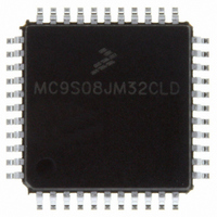
MC9S08JM32CLD Freescale Semiconductor, MC9S08JM32CLD Datasheet - Page 11

MC9S08JM32CLD
Manufacturer Part Number
MC9S08JM32CLD
Description
IC MCU 8BIT 32K FLASH 44-LQFP
Manufacturer
Freescale Semiconductor
Series
HCS08r
Datasheet
1.MC9S08JM32CLD.pdf
(388 pages)
Specifications of MC9S08JM32CLD
Core Processor
HCS08
Core Size
8-Bit
Speed
48MHz
Connectivity
I²C, LIN, SCI, SPI, USB
Peripherals
LVD, POR, PWM, WDT
Number Of I /o
33
Program Memory Size
32KB (32K x 8)
Program Memory Type
FLASH
Ram Size
2K x 8
Voltage - Supply (vcc/vdd)
2.7 V ~ 5.5 V
Data Converters
A/D 8x12b
Oscillator Type
External
Operating Temperature
-40°C ~ 85°C
Package / Case
44-LQFP
Processor Series
S08JM
Core
HCS08
Data Bus Width
8 bit
Data Ram Size
2 KB
Interface Type
SCI/SPI
Maximum Clock Frequency
24 MHz
Number Of Programmable I/os
33
Number Of Timers
8
Maximum Operating Temperature
+ 85 C
Mounting Style
SMD/SMT
3rd Party Development Tools
EWS08
Development Tools By Supplier
DEMOJM, DEMOJMSKT, DEMOFLEXISJMSD, DEMO9S08JM16
Minimum Operating Temperature
- 40 C
On-chip Adc
8-ch x 12-bit
Lead Free Status / RoHS Status
Lead free / RoHS Compliant
Eeprom Size
-
Lead Free Status / Rohs Status
Lead free / RoHS Compliant
Available stocks
Company
Part Number
Manufacturer
Quantity
Price
Company:
Part Number:
MC9S08JM32CLD
Manufacturer:
Freescale Semiconductor
Quantity:
1 948
Company:
Part Number:
MC9S08JM32CLD
Manufacturer:
Freescale Semiconductor
Quantity:
10 000
- Current page: 11 of 388
- Download datasheet (5Mb)
6.3
6.4
6.5
7.1
7.2
7.3
7.4
7.5
Freescale Semiconductor
Pin Control ......................................................................................................................................82
Pin Behavior in Stop Modes ............................................................................................................83
Parallel I/O and Pin Control Registers ............................................................................................83
Introduction .....................................................................................................................................99
Programmer’s Model and CPU Registers .....................................................................................100
Addressing Modes .........................................................................................................................103
Special Operations .........................................................................................................................105
HCS08 Instruction Set Summary ..................................................................................................108
6.3.1 Internal Pullup Enable ......................................................................................................83
6.3.2 Output Slew Rate Control Enable .....................................................................................83
6.3.3 Output Drive Strength Select ............................................................................................83
6.5.1 Port A I/O Registers (PTAD and PTADD) ........................................................................84
6.5.2 Port A Pin Control Registers (PTAPE, PTASE, PTADS) .................................................84
6.5.3 Port B I/O Registers (PTBD and PTBDD) ........................................................................86
6.5.4 Port B Pin Control Registers (PTBPE, PTBSE, PTBDS) .................................................86
6.5.5 Port C I/O Registers (PTCD and PTCDD) ........................................................................88
6.5.6 Port C Pin Control Registers (PTCPE, PTCSE, PTCDS) .................................................88
6.5.7 Port D I/O Registers (PTDD and PTDDD) .......................................................................90
6.5.8 Port D Pin Control Registers (PTDPE, PTDSE, PTDDS) ................................................90
6.5.9 Port E I/O Registers (PTED and PTEDD) ........................................................................92
6.5.10 Port E Pin Control Registers (PTEPE, PTESE, PTEDS) ..................................................92
6.5.11 Port F I/O Registers (PTFD and PTFDD) .........................................................................94
6.5.12 Port F Pin Control Registers (PTFPE, PTFSE, PTFDS) ...................................................94
6.5.13 Port G I/O Registers (PTGD and PTGDD) .......................................................................96
6.5.14 Port G Pin Control Registers (PTGPE, PTGSE, PTGDS) ................................................96
7.1.1 Features .............................................................................................................................99
7.2.1 Accumulator (A) .............................................................................................................100
7.2.2 Index Register (H:X) ......................................................................................................100
7.2.3 Stack Pointer (SP) ...........................................................................................................101
7.2.4 Program Counter (PC) ....................................................................................................101
7.2.5 Condition Code Register (CCR) .....................................................................................101
7.3.1 Inherent Addressing Mode (INH) ...................................................................................103
7.3.2 Relative Addressing Mode (REL) ..................................................................................103
7.3.3 Immediate Addressing Mode (IMM) ..............................................................................103
7.3.4 Direct Addressing Mode (DIR) ......................................................................................103
7.3.5 Extended Addressing Mode (EXT) ................................................................................104
7.3.6 Indexed Addressing Mode ..............................................................................................104
7.4.1 Reset Sequence ...............................................................................................................105
7.4.2 Interrupt Sequence ..........................................................................................................105
7.4.3 Wait Mode Operation ......................................................................................................106
7.4.4 Stop Mode Operation ......................................................................................................106
7.4.5 BGND Instruction ...........................................................................................................107
Central Processor Unit (S08CPUV2)
MC9S08JM60 Series Data Sheet, Rev. 3
Chapter 7
11
Related parts for MC9S08JM32CLD
Image
Part Number
Description
Manufacturer
Datasheet
Request
R
Part Number:
Description:
Manufacturer:
Freescale Semiconductor, Inc
Datasheet:
Part Number:
Description:
Manufacturer:
Freescale Semiconductor, Inc
Datasheet:
Part Number:
Description:
Manufacturer:
Freescale Semiconductor, Inc
Datasheet:
Part Number:
Description:
Manufacturer:
Freescale Semiconductor, Inc
Datasheet:
Part Number:
Description:
Manufacturer:
Freescale Semiconductor, Inc
Datasheet:
Part Number:
Description:
Manufacturer:
Freescale Semiconductor, Inc
Datasheet:
Part Number:
Description:
Manufacturer:
Freescale Semiconductor, Inc
Datasheet:
Part Number:
Description:
Manufacturer:
Freescale Semiconductor, Inc
Datasheet:
Part Number:
Description:
Manufacturer:
Freescale Semiconductor, Inc
Datasheet:
Part Number:
Description:
Manufacturer:
Freescale Semiconductor, Inc
Datasheet:
Part Number:
Description:
Manufacturer:
Freescale Semiconductor, Inc
Datasheet:
Part Number:
Description:
Manufacturer:
Freescale Semiconductor, Inc
Datasheet:
Part Number:
Description:
Manufacturer:
Freescale Semiconductor, Inc
Datasheet:
Part Number:
Description:
Manufacturer:
Freescale Semiconductor, Inc
Datasheet:
Part Number:
Description:
Manufacturer:
Freescale Semiconductor, Inc
Datasheet:


