C8051F021-GQ Silicon Laboratories Inc, C8051F021-GQ Datasheet - Page 11
C8051F021-GQ
Manufacturer Part Number
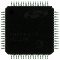
C8051F021-GQ
Description
IC 8051 MCU 64K FLASH 64TQFP
Manufacturer
Silicon Laboratories Inc
Series
C8051F02xr
Specifications of C8051F021-GQ
Program Memory Type
FLASH
Program Memory Size
64KB (64K x 8)
Package / Case
64-TQFP, 64-VQFP
Core Processor
8051
Core Size
8-Bit
Speed
25MHz
Connectivity
EBI/EMI, SMBus (2-Wire/I²C), SPI, UART/USART
Peripherals
Brown-out Detect/Reset, POR, PWM, Temp Sensor, WDT
Number Of I /o
32
Ram Size
4.25K x 8
Voltage - Supply (vcc/vdd)
2.7 V ~ 3.6 V
Data Converters
A/D 8x8b, 8x12b; D/A 2x12b
Oscillator Type
Internal
Operating Temperature
-40°C ~ 85°C
Processor Series
C8051F0x
Core
8051
Data Bus Width
8 bit
Data Ram Size
4.25 KB
Interface Type
I2C/SMBus/SPI/UART
Maximum Clock Frequency
25 MHz
Number Of Programmable I/os
32
Number Of Timers
4
Operating Supply Voltage
2.7 V to 3.6 V
Maximum Operating Temperature
+ 85 C
Mounting Style
SMD/SMT
3rd Party Development Tools
PK51, CA51, A51, ULINK2
Development Tools By Supplier
C8051F020DK
Minimum Operating Temperature
- 40 C
On-chip Adc
8-ch x 8-bit or 8-ch x 12-bit
On-chip Dac
2-ch x 12-bit
No. Of I/o's
32
Ram Memory Size
4352Byte
Cpu Speed
25MHz
No. Of Timers
5
No. Of Pwm Channels
5
Rohs Compliant
Yes
Data Rom Size
64 KB
A/d Bit Size
12 bit
A/d Channels Available
8
Height
1.05 mm
Length
10 mm
Supply Voltage (max)
3.6 V
Supply Voltage (min)
2.7 V
Width
10 mm
Lead Free Status / RoHS Status
Lead free / RoHS Compliant
For Use With
336-1200 - DEV KIT FOR F020/F021/F022/F023
Eeprom Size
-
Lead Free Status / Rohs Status
Lead free / RoHS Compliant
Other names
336-1201
Available stocks
Company
Part Number
Manufacturer
Quantity
Price
Company:

Part Number:
C8051F021-GQ
Manufacturer:
Silicon Laboratories Inc
Quantity:
10 000
Company:
Part Number:
C8051F021-GQR
Manufacturer:
SiliconL
Quantity:
2 000
Company:
Part Number:
C8051F021-GQR
Manufacturer:
Silicon Laboratories Inc
Quantity:
10 000
Part Number:
C8051F021-GQR
Manufacturer:
SILICON LABS/芯科
Quantity:
20 000


10. VOLTAGE REFERENCE (C8051F021/3)..........................................................................93
11. COMPARATORS..................................................................................................................95
12. CIP-51 MICROCONTROLLER........................................................................................101
13. RESET SOURCES ..............................................................................................................127
14. OSCILLATORS...................................................................................................................135
15. FLASH MEMORY ..............................................................................................................139
Figure 9.1. Voltage Reference Functional Block Diagram....................................................91
Figure 9.2. REF0CN: Reference Control Register ................................................................92
Table 9.1.
Figure 10.1. Voltage Reference Functional Block Diagram ...................................................93
Figure 10.2. REF0CN: Reference Control Register ................................................................94
Table 10.1. Voltage Reference Electrical Characteristics ......................................................94
Figure 11.1. Comparator Functional Block Diagram ..............................................................95
Figure 11.2. Comparator Hysteresis Plot.................................................................................96
Figure 11.3. CPT0CN: Comparator0 Control Register ...........................................................97
Figure 11.4. CPT1CN: Comparator1 Control Register ...........................................................98
Table 11.1. Comparator Electrical Characteristics.................................................................99
Figure 12.1. CIP-51 Block Diagram ......................................................................................101
Table 12.1. CIP-51 Instruction Set Summary.......................................................................103
Figure 12.2. Memory Map .....................................................................................................107
Table 12.2. Special Function Register (SFR) Memory Map................................................109
Table 12.3. Special Function Registers ................................................................................109
Figure 12.3. SP: Stack Pointer ...............................................................................................113
Figure 12.4. DPL: Data Pointer Low Byte ............................................................................113
Figure 12.5. DPH: Data Pointer High Byte ...........................................................................113
Figure 12.6. PSW: Program Status Word ..............................................................................114
Figure 12.7. ACC: Accumulator............................................................................................115
Figure 12.8. B: B Register .....................................................................................................115
Table 12.4. Interrupt Summary.............................................................................................117
Figure 12.9. IE: Interrupt Enable ...........................................................................................119
Figure 12.10. IP: Interrupt Priority ........................................................................................120
Figure 12.11. EIE1: Extended Interrupt Enable 1 .................................................................121
Figure 12.12. EIE2: Extended Interrupt Enable 2 .................................................................122
Figure 12.13. EIP1: Extended Interrupt Priority 1.................................................................123
Figure 12.14. EIP2: Extended Interrupt Priority 2.................................................................124
Figure 12.15. PCON: Power Control.....................................................................................126
Figure 13.1. Reset Sources ....................................................................................................127
Figure 13.2. Reset Timing .....................................................................................................128
Figure 13.3. WDTCN: Watchdog Timer Control Register ...................................................131
Figure 13.4. RSTSRC: Reset Source Register.......................................................................132
Table 13.1. Reset Electrical Characteristics .........................................................................133
Figure 14.1. Oscillator Diagram ............................................................................................135
Figure 14.2. OSCICN: Internal Oscillator Control Register .................................................136
Table 14.1. Internal Oscillator Electrical Characteristics.....................................................136
Figure 14.3. OSCXCN: External Oscillator Control Register...............................................137
Voltage Reference Electrical Characteristics ......................................................92
Rev. 1.4
C8051F020/1/2/3
11
Related parts for C8051F021-GQ
Image
Part Number
Description
Manufacturer
Datasheet
Request
R

Part Number:
Description:
SMD/C°/SINGLE-ENDED OUTPUT SILICON OSCILLATOR
Manufacturer:
Silicon Laboratories Inc
Part Number:
Description:
Manufacturer:
Silicon Laboratories Inc
Datasheet:
Part Number:
Description:
N/A N/A/SI4010 AES KEYFOB DEMO WITH LCD RX
Manufacturer:
Silicon Laboratories Inc
Datasheet:
Part Number:
Description:
N/A N/A/SI4010 SIMPLIFIED KEY FOB DEMO WITH LED RX
Manufacturer:
Silicon Laboratories Inc
Datasheet:
Part Number:
Description:
N/A/-40 TO 85 OC/EZLINK MODULE; F930/4432 HIGH BAND (REV E/B1)
Manufacturer:
Silicon Laboratories Inc
Part Number:
Description:
EZLink Module; F930/4432 Low Band (rev e/B1)
Manufacturer:
Silicon Laboratories Inc
Part Number:
Description:
I°/4460 10 DBM RADIO TEST CARD 434 MHZ
Manufacturer:
Silicon Laboratories Inc
Part Number:
Description:
I°/4461 14 DBM RADIO TEST CARD 868 MHZ
Manufacturer:
Silicon Laboratories Inc
Part Number:
Description:
I°/4463 20 DBM RFSWITCH RADIO TEST CARD 460 MHZ
Manufacturer:
Silicon Laboratories Inc
Part Number:
Description:
I°/4463 20 DBM RADIO TEST CARD 868 MHZ
Manufacturer:
Silicon Laboratories Inc
Part Number:
Description:
I°/4463 27 DBM RADIO TEST CARD 868 MHZ
Manufacturer:
Silicon Laboratories Inc
Part Number:
Description:
I°/4463 SKYWORKS 30 DBM RADIO TEST CARD 915 MHZ
Manufacturer:
Silicon Laboratories Inc
Part Number:
Description:
N/A N/A/-40 TO 85 OC/4463 RFMD 30 DBM RADIO TEST CARD 915 MHZ
Manufacturer:
Silicon Laboratories Inc
Part Number:
Description:
I°/4463 20 DBM RADIO TEST CARD 169 MHZ
Manufacturer:
Silicon Laboratories Inc