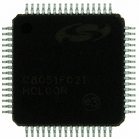
C8051F021-GQ Silicon Laboratories Inc, C8051F021-GQ Datasheet - Page 9

C8051F021-GQ
Manufacturer Part Number
C8051F021-GQ
Description
IC 8051 MCU 64K FLASH 64TQFP
Manufacturer
Silicon Laboratories Inc
Series
C8051F02xr
Specifications of C8051F021-GQ
Program Memory Type
FLASH
Program Memory Size
64KB (64K x 8)
Package / Case
64-TQFP, 64-VQFP
Core Processor
8051
Core Size
8-Bit
Speed
25MHz
Connectivity
EBI/EMI, SMBus (2-Wire/I²C), SPI, UART/USART
Peripherals
Brown-out Detect/Reset, POR, PWM, Temp Sensor, WDT
Number Of I /o
32
Ram Size
4.25K x 8
Voltage - Supply (vcc/vdd)
2.7 V ~ 3.6 V
Data Converters
A/D 8x8b, 8x12b; D/A 2x12b
Oscillator Type
Internal
Operating Temperature
-40°C ~ 85°C
Processor Series
C8051F0x
Core
8051
Data Bus Width
8 bit
Data Ram Size
4.25 KB
Interface Type
I2C/SMBus/SPI/UART
Maximum Clock Frequency
25 MHz
Number Of Programmable I/os
32
Number Of Timers
4
Operating Supply Voltage
2.7 V to 3.6 V
Maximum Operating Temperature
+ 85 C
Mounting Style
SMD/SMT
3rd Party Development Tools
PK51, CA51, A51, ULINK2
Development Tools By Supplier
C8051F020DK
Minimum Operating Temperature
- 40 C
On-chip Adc
8-ch x 8-bit or 8-ch x 12-bit
On-chip Dac
2-ch x 12-bit
No. Of I/o's
32
Ram Memory Size
4352Byte
Cpu Speed
25MHz
No. Of Timers
5
No. Of Pwm Channels
5
Rohs Compliant
Yes
Data Rom Size
64 KB
A/d Bit Size
12 bit
A/d Channels Available
8
Height
1.05 mm
Length
10 mm
Supply Voltage (max)
3.6 V
Supply Voltage (min)
2.7 V
Width
10 mm
Lead Free Status / RoHS Status
Lead free / RoHS Compliant
For Use With
336-1200 - DEV KIT FOR F020/F021/F022/F023
Eeprom Size
-
Lead Free Status / Rohs Status
Lead free / RoHS Compliant
Other names
336-1201
Available stocks
Company
Part Number
Manufacturer
Quantity
Price
Company:
Part Number:
C8051F021-GQ
Manufacturer:
Silicon Laboratories Inc
Quantity:
10 000
Company:
Part Number:
C8051F021-GQR
Manufacturer:
SiliconL
Quantity:
2 000
Company:
Part Number:
C8051F021-GQR
Manufacturer:
Silicon Laboratories Inc
Quantity:
10 000
Part Number:
C8051F021-GQR
Manufacturer:
SILICON LABS/芯科
Quantity:
20 000
LIST OF FIGURES AND TABLES
1. SYSTEM OVERVIEW .........................................................................................................17
2. ABSOLUTE MAXIMUM RATINGS ..................................................................................31
3. GLOBAL DC ELECTRICAL CHARACTERISTICS ......................................................32
4. PINOUT AND PACKAGE DEFINITIONS........................................................................33
5. ADC0 (12-BIT ADC, C8051F020/1 ONLY) ........................................................................43
Table 1.1.
Figure 1.1. C8051F020 Block Diagram.................................................................................18
Figure 1.2. C8051F021 Block Diagram.................................................................................19
Figure 1.3. C8051F022 Block Diagram.................................................................................20
Figure 1.4. C8051F023 Block Diagram.................................................................................21
Figure 1.5. Comparison of Peak MCU Execution Speeds.....................................................22
Figure 1.6. On-Board Clock and Reset..................................................................................23
Figure 1.7. On-Chip Memory Map ........................................................................................24
Figure 1.8. Development/In-System Debug Diagram ...........................................................25
Figure 1.9. Digital Crossbar Diagram....................................................................................26
Figure 1.10. PCA Block Diagram............................................................................................27
Figure 1.11. 12-Bit ADC Block Diagram................................................................................28
Figure 1.12. 8-Bit ADC Diagram ............................................................................................29
Figure 1.13. Comparator and DAC Diagram...........................................................................30
Table 2.1.
Table 3.1.
Table 4.1.
Figure 4.1. TQFP-100 Pinout Diagram..................................................................................38
Figure 4.2. TQFP-100 Package Drawing...............................................................................39
Figure 4.3. TQFP-64 Pinout Diagram....................................................................................40
Figure 4.4. TQFP-64 Package Drawing.................................................................................41
Figure 5.1. 12-Bit ADC0 Functional Block Diagram............................................................43
Figure 5.2. Temperature Sensor Transfer Function ...............................................................44
Figure 5.3. 12-Bit ADC Track and Conversion Example Timing.........................................45
Figure 5.4. ADC0 Equivalent Input Circuits .........................................................................46
Figure 5.5. AMX0CF: AMUX0 Configuration Register (C8051F020/1) .............................47
Figure 5.6. AMX0SL: AMUX0 Channel Select Register (C8051F020/1)............................48
Figure 5.7. ADC0CF: ADC0 Configuration Register (C8051F020/1)..................................49
Figure 5.8. ADC0CN: ADC0 Control Register (C8051F020/1) ...........................................50
Figure 5.9. ADC0H: ADC0 Data Word MSB Register (C8051F020/1) ...............................51
Figure 5.10. ADC0L: ADC0 Data Word LSB Register (C8051F020/1).................................51
Figure 5.11. ADC0 Data Word Example (C8051F020/1) .......................................................52
Figure 5.12. ADC0GTH: ADC0 Greater-Than Data High Byte Register (C8051F020/1) .....53
Figure 5.13. ADC0GTL: ADC0 Greater-Than Data Low Byte Register (C8051F020/1) ......53
Figure 5.14. ADC0LTH: ADC0 Less-Than Data High Byte Register (C8051F020/1) ..........53
Figure 5.15. ADC0LTL: ADC0 Less-Than Data Low Byte Register (C8051F020/1) ...........53
Figure 5.16. 12-Bit ADC0 Window Interrupt Example: Right Justified Single-Ended Data .54
Product Selection Guide ......................................................................................17
Absolute Maximum Ratings*..............................................................................31
Global DC Electrical Characteristics...................................................................32
Pin Definitions.....................................................................................................33
Rev. 1.4
C8051F020/1/2/3
9


