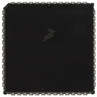
MC68HC711E9CFNE2 Freescale Semiconductor, MC68HC711E9CFNE2 Datasheet - Page 81

MC68HC711E9CFNE2
Manufacturer Part Number
MC68HC711E9CFNE2
Description
IC MCU 8BIT 512RAM 52-PLC
Manufacturer
Freescale Semiconductor
Series
HC11r
Datasheet
1.MC68HC711E9CFNE3.pdf
(336 pages)
Specifications of MC68HC711E9CFNE2
Core Processor
HC11
Core Size
8-Bit
Speed
2MHz
Connectivity
SCI, SPI
Peripherals
POR, WDT
Number Of I /o
38
Program Memory Size
12KB (12K x 8)
Program Memory Type
OTP
Eeprom Size
512 x 8
Ram Size
512 x 8
Voltage - Supply (vcc/vdd)
4.5 V ~ 5.5 V
Data Converters
A/D 8x8b
Oscillator Type
Internal
Operating Temperature
-40°C ~ 85°C
Package / Case
52-PLCC
Processor Series
HC711E
Core
HC11
Data Bus Width
8 bit
Data Ram Size
512 B
Interface Type
SCI, SPI
Maximum Clock Frequency
2 MHz
Number Of Programmable I/os
38
Number Of Timers
8
Maximum Operating Temperature
+ 85 C
Mounting Style
SMD/SMT
Minimum Operating Temperature
- 40 C
On-chip Adc
8 bit
Lead Free Status / RoHS Status
Lead free / RoHS Compliant
Available stocks
Company
Part Number
Manufacturer
Quantity
Price
Company:
Part Number:
MC68HC711E9CFNE2
Manufacturer:
TE
Quantity:
12 000
Company:
Part Number:
MC68HC711E9CFNE2
Manufacturer:
FREESCAL
Quantity:
5 530
- Current page: 81 of 336
- Download datasheet (4Mb)
M68HC11E Family — Rev. 3.2
MOTOROLA
The bootloader program is contained in the internal bootstrap ROM. This
ROM, which appears as internal memory space at locations
$BF00–$BFFF, is enabled only if the MCU is reset in special bootstrap
mode.
In expanded modes, the ROM/EPROM/OTPROM (if present) is enabled
out of reset and located at the top of the memory map if the ROMON bit
in the CONFIG register is set. ROM or EPROM is enabled out of reset in
single-chip and bootstrap modes, regardless of the state of ROMON.
For devices with 512 bytes of EEPROM, the EEPROM is located at
$B600–$B7FF and has the same read cycle time as the internal ROM.
The 512 bytes of EEPROM cannot be remapped to other locations.
For the MC68HC811E2, EEPROM is located at $F800–$FFFF and can
be remapped to any 4-Kbyte boundary. EEPROM mapping control bits
(EE[3:0] in CONFIG) determine the location of the 2048 bytes of
EEPROM and are present only on the MC68HC811E2. Refer to
4.4.3.1 System Configuration Register
MC68HC811E2 CONFIG register.
EEPROM can be programmed or erased by software and an on-chip
charge pump, allowing EEPROM changes using the single V
Operating Modes and On-Chip Memory
Figure 4-8. RAM Standby MODB/V
4.8-V
NiCd
V
DD
+
V
V
DD
BATT
MAX
690
V
OUT
Operating Modes and On-Chip Memory
4.7 k
for a description of the
STBY
Connections
TO MODB/V
OF M68HC11
STBY
Technical Data
Memory Map
DD
supply.
81
Related parts for MC68HC711E9CFNE2
Image
Part Number
Description
Manufacturer
Datasheet
Request
R

Part Number:
Description:
APPENDIX A ELECTRICAL CHARACTERISTICS
Manufacturer:
FREESCALE [Freescale Semiconductor, Inc]
Datasheet:
Part Number:
Description:
Manufacturer:
Freescale Semiconductor, Inc
Datasheet:
Part Number:
Description:
Manufacturer:
Freescale Semiconductor, Inc
Datasheet:
Part Number:
Description:
Manufacturer:
Freescale Semiconductor, Inc
Datasheet:
Part Number:
Description:
Manufacturer:
Freescale Semiconductor, Inc
Datasheet:
Part Number:
Description:
Manufacturer:
Freescale Semiconductor, Inc
Datasheet:
Part Number:
Description:
Manufacturer:
Freescale Semiconductor, Inc
Datasheet:
Part Number:
Description:
Manufacturer:
Freescale Semiconductor, Inc
Datasheet:
Part Number:
Description:
Manufacturer:
Freescale Semiconductor, Inc
Datasheet:
Part Number:
Description:
Manufacturer:
Freescale Semiconductor, Inc
Datasheet:
Part Number:
Description:
Manufacturer:
Freescale Semiconductor, Inc
Datasheet:
Part Number:
Description:
Manufacturer:
Freescale Semiconductor, Inc
Datasheet:
Part Number:
Description:
Manufacturer:
Freescale Semiconductor, Inc
Datasheet:
Part Number:
Description:
Manufacturer:
Freescale Semiconductor, Inc
Datasheet:
Part Number:
Description:
Manufacturer:
Freescale Semiconductor, Inc
Datasheet:


