MPC8572DS Freescale Semiconductor, MPC8572DS Datasheet - Page 123
MPC8572DS
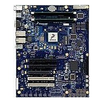
Manufacturer Part Number
MPC8572DS
Description
KIT MPU POWERQUICC III
Manufacturer
Freescale Semiconductor
Series
PowerQUICC III™r
Type
MPUr
Specifications of MPC8572DS
Contents
Board
Data Rate
10 Mbps to 100 Mbps
Memory Type
Flash, DDR, DDR2, DDR3, SDRAM
Interface Type
I2C, Ethernet
Operating Voltage
3.3 V
Data Bus Width
32 bit
Product
Development Tools
Silicon Manufacturer
Freescale
Core Architecture
Power Architecture
Core Sub-architecture
PowerQUICC
Silicon Core Number
MPC85xx
Silicon Family Name
PowerQUICC III
Rohs Compliant
Yes
For Use With/related Products
MPC8572E
Lead Free Status / RoHS Status
Lead free / RoHS Compliant


The ratio of I
Solving for T, the equation becomes:
21 System Design Information
This section provides electrical and thermal design recommendations for successful application of the
MPC8572E.
21.1
The platform PLL generates the platform clock from the externally supplied SYSCLK input. The
frequency ratio between the platform and SYSCLK is selected using the platform PLL ratio configuration
bits as described in
the following functions:
Freescale Semiconductor
•
•
•
•
•
V
nT =
V
V
V
I
I
q = Charge of electron (1.6 x 10
n = Ideality factor (normally 1.0)
K = Boltzman’s constant (1.38 x 10
T = Temperature (Kelvins)
H
H
L
f
H
L
– V
Two core PLLs have ratios that are individually configurable. Each e500 core PLL generates the
core clock as a slave to the platform clock. The frequency ratio between the e500 core clock and
the platform clock is selected using the e500 PLL ratio configuration bits as described in
Section 19.3, “e500 Core PLL Ratio.”
The DDR complex PLL generates the clocking for the DDR controllers.
The local bus PLL generates the clock for the local bus.
The PLL for the SerDes1 module is used for PCI Express and Serial Rapid IO interfaces.
The PLL for the SerDes2 module is used for the SGMII interface.
= Smaller diode bias current
= Larger diode bias current
= Voltage forward biased
= Diode voltage while I
= Diode voltage while I
System Clocking
L
= 1.986 × 10
H
__________
1.986 × 10
to I
V
MPC8572E PowerQUICC III Integrated Processor Hardware Specifications, Rev. 5
H
L
Section 19.2, “CCB/SYSCLK PLL Ratio.”
– V
is usually selected to be 10:1. The above simplifies to the following:
L
–4
–4
× nT
L
H
is flowing
is flowing
–19
–23
C)
Joules/K)
The MPC8572E includes seven PLLs, with
System Design Information
123
Related parts for MPC8572DS
Image
Part Number
Description
Manufacturer
Datasheet
Request
R

Part Number:
Description:
Manufacturer:
Freescale Semiconductor, Inc
Datasheet:
Part Number:
Description:
Manufacturer:
Freescale Semiconductor, Inc
Datasheet:
Part Number:
Description:
Manufacturer:
Freescale Semiconductor, Inc
Datasheet:
Part Number:
Description:
Manufacturer:
Freescale Semiconductor, Inc
Datasheet:
Part Number:
Description:
Manufacturer:
Freescale Semiconductor, Inc
Datasheet:
Part Number:
Description:
Manufacturer:
Freescale Semiconductor, Inc
Datasheet:
Part Number:
Description:
Manufacturer:
Freescale Semiconductor, Inc
Datasheet:
Part Number:
Description:
Manufacturer:
Freescale Semiconductor, Inc
Datasheet:
Part Number:
Description:
Manufacturer:
Freescale Semiconductor, Inc
Datasheet:
Part Number:
Description:
Manufacturer:
Freescale Semiconductor, Inc
Datasheet:
Part Number:
Description:
Manufacturer:
Freescale Semiconductor, Inc
Datasheet:
Part Number:
Description:
Manufacturer:
Freescale Semiconductor, Inc
Datasheet:
Part Number:
Description:
Manufacturer:
Freescale Semiconductor, Inc
Datasheet:
Part Number:
Description:
Manufacturer:
Freescale Semiconductor, Inc
Datasheet:
Part Number:
Description:
Manufacturer:
Freescale Semiconductor, Inc
Datasheet: