MPC8572DS Freescale Semiconductor, MPC8572DS Datasheet - Page 87
MPC8572DS
Manufacturer Part Number
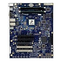
MPC8572DS
Description
KIT MPU POWERQUICC III
Manufacturer
Freescale Semiconductor
Series
PowerQUICC III™r
Type
MPUr
Specifications of MPC8572DS
Contents
Board
Data Rate
10 Mbps to 100 Mbps
Memory Type
Flash, DDR, DDR2, DDR3, SDRAM
Interface Type
I2C, Ethernet
Operating Voltage
3.3 V
Data Bus Width
32 bit
Product
Development Tools
Silicon Manufacturer
Freescale
Core Architecture
Power Architecture
Core Sub-architecture
PowerQUICC
Silicon Core Number
MPC85xx
Silicon Family Name
PowerQUICC III
Rohs Compliant
Yes
For Use With/related Products
MPC8572E
Lead Free Status / RoHS Status
Lead free / RoHS Compliant


Freescale Semiconductor
T
ENTERTIME
L
Notes:
1. No test load is necessarily associated with this value.
2. Specified at the measurement point and measured over any 250 consecutive UIs. The test load in
3. A T
4. The Receiver input impedance shall result in a differential return loss greater than or equal to 15 dB with the D+ line biased
5. Impedance during all LTSSM states. When transitioning from a Fundamental Reset to Detect (the initial state of the LTSSM)
6. The RX DC Common Mode Impedance that exists when no power is present or Fundamental Reset is asserted. This helps
7. It is recommended that the recovered TX UI is calculated using all edges in the 3500 consecutive UI interval with a fit algorithm
RX-SKEW
RX-IDLE-DET-DIFF-
as the RX device when taking measurements (also refer to the Receiver compliance eye diagram shown in
clocks to the RX and TX are not derived from the same reference clock, the TX UI recovered from 3500 consecutive UI must
be used as a reference for the eye diagram.
interconnect collected any 250 consecutive UIs. The T
in which the median and the maximum deviation from the median is less than half of the total. UI jitter budget collected over
any 250 consecutive TX UIs. It should be noted that the median is not the same as the mean. The jitter median describes the
point in time where the number of jitter points on either side is approximately equal as opposed to the averaged time value.
If the clocks to the RX and TX are not derived from the same reference clock, the TX UI recovered from 3500 consecutive UI
must be used as the reference for the eye diagram.
to 300 mV and the D- line biased to -300 mV and a common mode return loss greater than or equal to 6 dB (no bias required)
over a frequency range of 50 MHz to 1.25 GHz. This input impedance requirement applies to all valid input levels. The
reference impedance for return loss measurements for is 50 ohms to ground for both the D+ and D- line (that is, as measured
by a Vector Network Analyzer with 50 ohm probes - see
return loss measurement.
there is a 5 ms transition time before Receiver termination values must be met on all un-configured Lanes of a Port.
ensure that the Receiver Detect circuit does not falsely assume a Receiver is powered on when it is not. This term must be
measured at 300 mV above the RX ground.
using a minimization merit function. Least squares and median deviation fits have worked well with experimental and
simulated data.
RX-EYE
Symbol
= 0.40 UI provides for a total sum of 0.60 UI deterministic and random jitter budget for the Transmitter and
MPC8572E PowerQUICC III Integrated Processor Hardware Specifications, Rev. 5
Table 63. Differential Receiver (RX) Input Specifications (continued)
Unexpected
Electrical Idle
Enter Detect
Threshold
Integration Time
Total Skew
Parameter
Min
—
—
Nominal
—
—
RX-EYE-MEDIAN-to-MAX-JITTER
Figure
Max
10
20
57). Note: that the series capacitors CTX is optional for the
Units
ms
ns
An unexpected Electrical Idle (V
V
no longer than T
to signal an unexpected idle condition.
Skew across all lanes on a Link. This
includes variation in the length of SKP
ordered set (for example, COM and one to
five SKP Symbols) at the RX as well as any
delay differences arising from the
interconnect itself.
RX-IDLE-DET-DIFFp-p
specification ensures a jitter distribution
Comments
RX-IDLE-DET-DIFF-ENTERING
Figure 57
) must be recognized
Figure
should be used
RX-DIFFp-p
PCI Express
56). If the
87
<
Related parts for MPC8572DS
Image
Part Number
Description
Manufacturer
Datasheet
Request
R

Part Number:
Description:
Manufacturer:
Freescale Semiconductor, Inc
Datasheet:
Part Number:
Description:
Manufacturer:
Freescale Semiconductor, Inc
Datasheet:
Part Number:
Description:
Manufacturer:
Freescale Semiconductor, Inc
Datasheet:
Part Number:
Description:
Manufacturer:
Freescale Semiconductor, Inc
Datasheet:
Part Number:
Description:
Manufacturer:
Freescale Semiconductor, Inc
Datasheet:
Part Number:
Description:
Manufacturer:
Freescale Semiconductor, Inc
Datasheet:
Part Number:
Description:
Manufacturer:
Freescale Semiconductor, Inc
Datasheet:
Part Number:
Description:
Manufacturer:
Freescale Semiconductor, Inc
Datasheet:
Part Number:
Description:
Manufacturer:
Freescale Semiconductor, Inc
Datasheet:
Part Number:
Description:
Manufacturer:
Freescale Semiconductor, Inc
Datasheet:
Part Number:
Description:
Manufacturer:
Freescale Semiconductor, Inc
Datasheet:
Part Number:
Description:
Manufacturer:
Freescale Semiconductor, Inc
Datasheet:
Part Number:
Description:
Manufacturer:
Freescale Semiconductor, Inc
Datasheet:
Part Number:
Description:
Manufacturer:
Freescale Semiconductor, Inc
Datasheet:
Part Number:
Description:
Manufacturer:
Freescale Semiconductor, Inc
Datasheet: