MPC8572DS Freescale Semiconductor, MPC8572DS Datasheet - Page 89
MPC8572DS
Manufacturer Part Number
MPC8572DS
Description
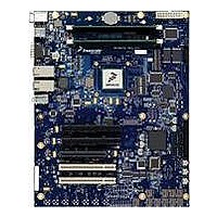
KIT MPU POWERQUICC III
Manufacturer
Freescale Semiconductor
Series
PowerQUICC III™r
Type
MPUr
Specifications of MPC8572DS
Contents
Board
Data Rate
10 Mbps to 100 Mbps
Memory Type
Flash, DDR, DDR2, DDR3, SDRAM
Interface Type
I2C, Ethernet
Operating Voltage
3.3 V
Data Bus Width
32 bit
Product
Development Tools
Silicon Manufacturer
Freescale
Core Architecture
Power Architecture
Core Sub-architecture
PowerQUICC
Silicon Core Number
MPC85xx
Silicon Family Name
PowerQUICC III
Rohs Compliant
Yes
For Use With/related Products
MPC8572E
Lead Free Status / RoHS Status
Lead free / RoHS Compliant


16.5.1
The AC timing and voltage parameters must be verified at the measurement point, as specified within 0.2
inches of the package pins, into a test/measurement load shown in
17 Serial RapidIO
This section describes the DC and AC electrical specifications for the RapidIO interface of the MPC8572E
for the LP-Serial physical layer. The electrical specifications cover both single and multiple-lane links.
Two transmitters (short run and long run) and a single receiver are specified for each of three baud rates,
1.25, 2.50, and 3.125 GBaud.
Two transmitter specifications allow for solutions ranging from simple board-to-board interconnect to
driving two connectors across a backplane. A single receiver specification is given that accepts signals
from both the short run and long run transmitter specifications.
The short run transmitter should be used mainly for chip-to-chip connections on either the same printed
circuit board or across a single connector. This covers the case where connections are made to a mezzanine
(daughter) card. The minimum swings of the short run specification reduce the overall power used by the
transceivers.
The long run transmitter specifications use larger voltage swings that are capable of driving signals across
backplanes. This allows a user to drive signals across two connectors and a backplane. The specifications
allow a distance of at least 50 cm at all baud rates.
All unit intervals are specified with a tolerance of +/– 100 ppm. The worst case frequency difference
between any transmit and receive clock is 200 ppm.
To ensure interoperability between drivers and receivers of different vendors and technologies, AC
coupling at the receiver input must be used.
Freescale Semiconductor
Compliance Test and Measurement Load
The allowance of the measurement point to be within 0.2 inches of the
package pins is meant to acknowledge that package/board routing may
benefit from D+ and D– not being exactly matched in length at the package
pin boundary.
MPC8572E PowerQUICC III Integrated Processor Hardware Specifications, Rev. 5
D+ Package
D+ Package
D– Package
Figure 57. Compliance Test/Measurement Load
+ Package
Silicon
Pin
Pin
Pin
TX
C = C
C = C
NOTE
R = 50 Ω
TX
TX
Figure
R = 50 Ω
57.
Serial RapidIO
89
Related parts for MPC8572DS
Image
Part Number
Description
Manufacturer
Datasheet
Request
R

Part Number:
Description:
Manufacturer:
Freescale Semiconductor, Inc
Datasheet:
Part Number:
Description:
Manufacturer:
Freescale Semiconductor, Inc
Datasheet:
Part Number:
Description:
Manufacturer:
Freescale Semiconductor, Inc
Datasheet:
Part Number:
Description:
Manufacturer:
Freescale Semiconductor, Inc
Datasheet:
Part Number:
Description:
Manufacturer:
Freescale Semiconductor, Inc
Datasheet:
Part Number:
Description:
Manufacturer:
Freescale Semiconductor, Inc
Datasheet:
Part Number:
Description:
Manufacturer:
Freescale Semiconductor, Inc
Datasheet:
Part Number:
Description:
Manufacturer:
Freescale Semiconductor, Inc
Datasheet:
Part Number:
Description:
Manufacturer:
Freescale Semiconductor, Inc
Datasheet:
Part Number:
Description:
Manufacturer:
Freescale Semiconductor, Inc
Datasheet:
Part Number:
Description:
Manufacturer:
Freescale Semiconductor, Inc
Datasheet:
Part Number:
Description:
Manufacturer:
Freescale Semiconductor, Inc
Datasheet:
Part Number:
Description:
Manufacturer:
Freescale Semiconductor, Inc
Datasheet:
Part Number:
Description:
Manufacturer:
Freescale Semiconductor, Inc
Datasheet:
Part Number:
Description:
Manufacturer:
Freescale Semiconductor, Inc
Datasheet: