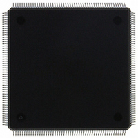
MCF5307AI90B Freescale Semiconductor, MCF5307AI90B Datasheet - Page 142

MCF5307AI90B
Manufacturer Part Number
MCF5307AI90B
Description
IC MPU 32BIT COLDF 90MHZ 208FQFP
Manufacturer
Freescale Semiconductor
Series
MCF530xr
Datasheets
1.MCF5307AI66B.pdf
(484 pages)
2.MCF5307AI66B.pdf
(16 pages)
3.MCF5307AI66B.pdf
(2 pages)
Specifications of MCF5307AI90B
Core Processor
Coldfire V3
Core Size
32-Bit
Speed
90MHz
Connectivity
EBI/EMI, I²C, UART/USART
Peripherals
DMA, POR, WDT
Number Of I /o
16
Program Memory Type
ROMless
Ram Size
4K x 8
Voltage - Supply (vcc/vdd)
3 V ~ 3.6 V
Oscillator Type
External
Operating Temperature
0°C ~ 70°C
Package / Case
208-FQFP
Maximum Clock Frequency
90 MHz
Maximum Operating Temperature
+ 105 C
Mounting Style
SMD/SMT
Minimum Operating Temperature
0 C
Family Name
MCF5xxx
Device Core
ColdFire
Device Core Size
32b
Frequency (max)
90MHz
Instruction Set Architecture
RISC
Supply Voltage 1 (typ)
3.3V
Operating Temp Range
0C to 70C
Operating Temperature Classification
Commercial
Mounting
Surface Mount
Pin Count
208
Package Type
FQFP
Program Memory Size
8KB
Cpu Speed
90MHz
Embedded Interface Type
I2C, UART
Digital Ic Case Style
FQFP
No. Of Pins
208
Supply Voltage Range
3V To 3.6V
Rohs Compliant
Yes
Lead Free Status / RoHS Status
Lead free / RoHS Compliant
Eeprom Size
-
Program Memory Size
-
Data Converters
-
Lead Free Status / Rohs Status
Lead free / RoHS Compliant
Available stocks
Company
Part Number
Manufacturer
Quantity
Price
Company:
Part Number:
MCF5307AI90B
Manufacturer:
FREESCAL
Quantity:
153
Company:
Part Number:
MCF5307AI90B
Manufacturer:
Freescale Semiconductor
Quantity:
10 000
Part Number:
MCF5307AI90B
Manufacturer:
FREESCALE
Quantity:
20 000
- Current page: 142 of 484
- Download datasheet (6Mb)
Programming Model
Table 5-12 describes PBR fields.
Figure 5-11 shows PBMR.
Table 5-13 describes PBMR fields.
5.4.7 Trigger Definition Register (TDR)
The TDR, shown in Table 5-12, configures the operation of the hardware breakpoint logic
that corresponds with the ABHR/ABLR/AATR, PBR/PBMR, and DBR/DBMR registers
within the debug module. The TDR controls the actions taken under the defined conditions.
Breakpoint logic may be configured as a one- or two-level trigger. TDR[31–16] define the
second-level trigger and bits 15–0 define the first-level trigger.
DRc[4–0]
5-14
31–0 Mask
31–0 Address PC breakpoint address. The 32-bit address to be compared with the PC as a breakpoint trigger.
Bits
Bits
DRc[4–0]
Reset
Field
R/W Write. PC breakpoint register is accessible in supervisor mode using the WDEBUG instruction and through
Reset
Field
R/W
Name
Name
the BDM port using the
Set Descriptions.”
31
Figure 5-11. Program Counter Breakpoint Mask Register (PBMR)
31
Write. PBMR is accessible in supervisor mode as debug control register 0x09 using the WDEBUG
PC breakpoint mask. A zero in a bit position causes the corresponding PBR bit to be compared to
the appropriate PC bit. Set PBMR bits cause PBR bits to be ignored.
Figure 5-10. Program Counter Breakpoint Register (PBR)
Freescale Semiconductor, Inc.
Table 5-13. PBMR Field Descriptions
instruction and via the BDM port using the wdmreg command.
For More Information On This Product,
RDMREG
Table 5-12. PBR Field Descriptions
and
Go to: www.freescale.com
MCF5307 User’s Manual
WDMREG
Program Counter
commands using values shown in Section 5.5.3.3, “Command
Description
Description
Mask
0x08
0x09
—
—
1
0
0
Related parts for MCF5307AI90B
Image
Part Number
Description
Manufacturer
Datasheet
Request
R
Part Number:
Description:
Manufacturer:
Freescale Semiconductor, Inc
Datasheet:
Part Number:
Description:
Mcf5307 Coldfire Integrated Microprocessor User
Manufacturer:
Freescale Semiconductor, Inc
Datasheet:
Part Number:
Description:
Manufacturer:
Freescale Semiconductor, Inc
Datasheet:
Part Number:
Description:
Manufacturer:
Freescale Semiconductor, Inc
Datasheet:
Part Number:
Description:
Manufacturer:
Freescale Semiconductor, Inc
Datasheet:
Part Number:
Description:
Manufacturer:
Freescale Semiconductor, Inc
Datasheet:
Part Number:
Description:
Manufacturer:
Freescale Semiconductor, Inc
Datasheet:
Part Number:
Description:
Manufacturer:
Freescale Semiconductor, Inc
Datasheet:
Part Number:
Description:
Manufacturer:
Freescale Semiconductor, Inc
Datasheet:
Part Number:
Description:
Manufacturer:
Freescale Semiconductor, Inc
Datasheet:
Part Number:
Description:
Manufacturer:
Freescale Semiconductor, Inc
Datasheet:
Part Number:
Description:
Manufacturer:
Freescale Semiconductor, Inc
Datasheet:
Part Number:
Description:
Manufacturer:
Freescale Semiconductor, Inc
Datasheet:
Part Number:
Description:
Manufacturer:
Freescale Semiconductor, Inc
Datasheet:
Part Number:
Description:
Manufacturer:
Freescale Semiconductor, Inc
Datasheet:


