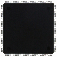
MCF5307AI90B Freescale Semiconductor, MCF5307AI90B Datasheet - Page 92

MCF5307AI90B
Manufacturer Part Number
MCF5307AI90B
Description
IC MPU 32BIT COLDF 90MHZ 208FQFP
Manufacturer
Freescale Semiconductor
Series
MCF530xr
Datasheets
1.MCF5307AI66B.pdf
(484 pages)
2.MCF5307AI66B.pdf
(16 pages)
3.MCF5307AI66B.pdf
(2 pages)
Specifications of MCF5307AI90B
Core Processor
Coldfire V3
Core Size
32-Bit
Speed
90MHz
Connectivity
EBI/EMI, I²C, UART/USART
Peripherals
DMA, POR, WDT
Number Of I /o
16
Program Memory Type
ROMless
Ram Size
4K x 8
Voltage - Supply (vcc/vdd)
3 V ~ 3.6 V
Oscillator Type
External
Operating Temperature
0°C ~ 70°C
Package / Case
208-FQFP
Maximum Clock Frequency
90 MHz
Maximum Operating Temperature
+ 105 C
Mounting Style
SMD/SMT
Minimum Operating Temperature
0 C
Family Name
MCF5xxx
Device Core
ColdFire
Device Core Size
32b
Frequency (max)
90MHz
Instruction Set Architecture
RISC
Supply Voltage 1 (typ)
3.3V
Operating Temp Range
0C to 70C
Operating Temperature Classification
Commercial
Mounting
Surface Mount
Pin Count
208
Package Type
FQFP
Program Memory Size
8KB
Cpu Speed
90MHz
Embedded Interface Type
I2C, UART
Digital Ic Case Style
FQFP
No. Of Pins
208
Supply Voltage Range
3V To 3.6V
Rohs Compliant
Yes
Lead Free Status / RoHS Status
Lead free / RoHS Compliant
Eeprom Size
-
Program Memory Size
-
Data Converters
-
Lead Free Status / Rohs Status
Lead free / RoHS Compliant
Available stocks
Company
Part Number
Manufacturer
Quantity
Price
Company:
Part Number:
MCF5307AI90B
Manufacturer:
FREESCAL
Quantity:
153
Company:
Part Number:
MCF5307AI90B
Manufacturer:
Freescale Semiconductor
Quantity:
10 000
Part Number:
MCF5307AI90B
Manufacturer:
FREESCALE
Quantity:
20 000
- Current page: 92 of 484
- Download datasheet (6Mb)
Exception Processing Overview
If a ColdFire processor encounters any type of fault during the exception processing of
another fault, the processor immediately halts execution with the catastrophic fault-on-fault
condition. A reset is required to force the processor to exit this halted state.
2-52
Reset
Exception
Unsupported
Instruction
Exception
Exception
Asserting the reset input signal (RSTI) causes a reset exception. Reset has the highest exception
priority; it provides for system initialization and recovery from catastrophic failure. When assertion of
RSTI is recognized, current processing is aborted and cannot be recovered. The reset exception
places the processor in supervisor mode by setting SR[S] and disables tracing by clearing SR[T].
This exception also clears SR[M] and sets the processor’s interrupt priority mask in the SR to the
highest level (level 7). Next, the VBR is initialized to 0x0000_0000. Configuration registers controlling
the operation of all processor-local memories (cache and RAM modules on the MCF5307) are
invalidated, disabling the memories.
Note: Other implementation-specific supervisor registers are also affected. Refer to each of the
modules in this manual for details on these registers.
After RSTI is negated, the processor waits 80 cycles before beginning the actual reset exception
process. During this time, certain events are sampled, including the assertion of the debug
breakpoint signal. If the processor is not halted, it initiates the reset exception by performing two
longword read bus cycles. The longword at address 0 is loaded into the stack pointer and the
longword at address 4 is loaded into the PC. After the initial instruction is fetched from memory,
program execution begins at the address in the PC. If an access error or address error occurs before
the first instruction executes, the processor enters the fault-on-fault halted state.
If the MCF5307 attempts to execute a valid instruction but the required optional hardware module is
not present in the OEP, a non-supported instruction exception is generated (vector 0x61). Control is
then passed to an exception handler that can then process the opcode as required by the system.
Table 2-21. MCF5307 Exceptions (Continued)
Freescale Semiconductor, Inc.
For More Information On This Product,
Go to: www.freescale.com
MCF5307 User’s Manual
Description
Related parts for MCF5307AI90B
Image
Part Number
Description
Manufacturer
Datasheet
Request
R
Part Number:
Description:
Manufacturer:
Freescale Semiconductor, Inc
Datasheet:
Part Number:
Description:
Mcf5307 Coldfire Integrated Microprocessor User
Manufacturer:
Freescale Semiconductor, Inc
Datasheet:
Part Number:
Description:
Manufacturer:
Freescale Semiconductor, Inc
Datasheet:
Part Number:
Description:
Manufacturer:
Freescale Semiconductor, Inc
Datasheet:
Part Number:
Description:
Manufacturer:
Freescale Semiconductor, Inc
Datasheet:
Part Number:
Description:
Manufacturer:
Freescale Semiconductor, Inc
Datasheet:
Part Number:
Description:
Manufacturer:
Freescale Semiconductor, Inc
Datasheet:
Part Number:
Description:
Manufacturer:
Freescale Semiconductor, Inc
Datasheet:
Part Number:
Description:
Manufacturer:
Freescale Semiconductor, Inc
Datasheet:
Part Number:
Description:
Manufacturer:
Freescale Semiconductor, Inc
Datasheet:
Part Number:
Description:
Manufacturer:
Freescale Semiconductor, Inc
Datasheet:
Part Number:
Description:
Manufacturer:
Freescale Semiconductor, Inc
Datasheet:
Part Number:
Description:
Manufacturer:
Freescale Semiconductor, Inc
Datasheet:
Part Number:
Description:
Manufacturer:
Freescale Semiconductor, Inc
Datasheet:
Part Number:
Description:
Manufacturer:
Freescale Semiconductor, Inc
Datasheet:


