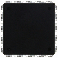
MCF5307AI90B Freescale Semiconductor, MCF5307AI90B Datasheet - Page 88

MCF5307AI90B
Manufacturer Part Number
MCF5307AI90B
Description
IC MPU 32BIT COLDF 90MHZ 208FQFP
Manufacturer
Freescale Semiconductor
Series
MCF530xr
Datasheets
1.MCF5307AI66B.pdf
(484 pages)
2.MCF5307AI66B.pdf
(16 pages)
3.MCF5307AI66B.pdf
(2 pages)
Specifications of MCF5307AI90B
Core Processor
Coldfire V3
Core Size
32-Bit
Speed
90MHz
Connectivity
EBI/EMI, I²C, UART/USART
Peripherals
DMA, POR, WDT
Number Of I /o
16
Program Memory Type
ROMless
Ram Size
4K x 8
Voltage - Supply (vcc/vdd)
3 V ~ 3.6 V
Oscillator Type
External
Operating Temperature
0°C ~ 70°C
Package / Case
208-FQFP
Maximum Clock Frequency
90 MHz
Maximum Operating Temperature
+ 105 C
Mounting Style
SMD/SMT
Minimum Operating Temperature
0 C
Family Name
MCF5xxx
Device Core
ColdFire
Device Core Size
32b
Frequency (max)
90MHz
Instruction Set Architecture
RISC
Supply Voltage 1 (typ)
3.3V
Operating Temp Range
0C to 70C
Operating Temperature Classification
Commercial
Mounting
Surface Mount
Pin Count
208
Package Type
FQFP
Program Memory Size
8KB
Cpu Speed
90MHz
Embedded Interface Type
I2C, UART
Digital Ic Case Style
FQFP
No. Of Pins
208
Supply Voltage Range
3V To 3.6V
Rohs Compliant
Yes
Lead Free Status / RoHS Status
Lead free / RoHS Compliant
Eeprom Size
-
Program Memory Size
-
Data Converters
-
Lead Free Status / Rohs Status
Lead free / RoHS Compliant
Available stocks
Company
Part Number
Manufacturer
Quantity
Price
Company:
Part Number:
MCF5307AI90B
Manufacturer:
FREESCAL
Quantity:
153
Company:
Part Number:
MCF5307AI90B
Manufacturer:
Freescale Semiconductor
Quantity:
10 000
Part Number:
MCF5307AI90B
Manufacturer:
FREESCALE
Quantity:
20 000
- Current page: 88 of 484
- Download datasheet (6Mb)
Exception Processing Overview
ColdFire processors support a 1024-byte vector table aligned on any 1-Mbyte address
boundary; see Table 2-18. The table contains 256 exception vectors where the first 64 are
defined by Motorola; the remaining 192 are user-defined interrupt vectors.
2-48
Vector Numbers
4. The processor acquires the address of the first instruction of the exception handler.
16–23
25–31
32–47
48–60
6–7
fixed-length stack frame for all exceptions. The exception type determines whether
the program counter in the exception stack frame defines the address of the faulting
instruction (fault) or of the next instruction to be executed (next).
The exception vector table is aligned on a 1-Mbyte boundary. This instruction
address is obtained by fetching a value from the table at the address defined in the
vector base register. The index into the exception table is calculated as
4 x vector_number. When the index value is generated, the vector table contents
determine the address of the first instruction of the desired handler. After the fetch
of the first opcode of the handler is initiated, exception processing terminates and
normal instruction processing continues in the handler.
10
11
12
13
14
15
24
61
0
1
2
3
4
5
8
9
Vector Offset (Hex)
080–0BC
0C0–0F0
Table 2-18. Exception Vector Assignments
018–01C
040–05C
064–07C
Freescale Semiconductor, Inc.
00C
02C
03C
000
004
008
010
014
020
024
028
030
034
038
060
0F4
For More Information On This Product,
Go to: www.freescale.com
MCF5307 User’s Manual
Stacked Program Counter
Fault
Fault
Fault
Fault
Fault
Fault
Fault
Fault
Fault
Next
Next
Next
Next
Next
Next
—
—
—
—
—
—
1
Initial stack pointer
Initial program counter
Access error
Address error
Illegal instruction
Divide by zero
Reserved
Privilege violation
Trace
Unimplemented line-a opcode
Unimplemented line-f opcode
Debug interrupt
Reserved
Format error
Uninitialized interrupt
Reserved
Spurious interrupt
Level 1–7 autovectored interrupts
Trap #0–15 instructions
Reserved
Unsupported instruction
Assignment
Related parts for MCF5307AI90B
Image
Part Number
Description
Manufacturer
Datasheet
Request
R
Part Number:
Description:
Manufacturer:
Freescale Semiconductor, Inc
Datasheet:
Part Number:
Description:
Mcf5307 Coldfire Integrated Microprocessor User
Manufacturer:
Freescale Semiconductor, Inc
Datasheet:
Part Number:
Description:
Manufacturer:
Freescale Semiconductor, Inc
Datasheet:
Part Number:
Description:
Manufacturer:
Freescale Semiconductor, Inc
Datasheet:
Part Number:
Description:
Manufacturer:
Freescale Semiconductor, Inc
Datasheet:
Part Number:
Description:
Manufacturer:
Freescale Semiconductor, Inc
Datasheet:
Part Number:
Description:
Manufacturer:
Freescale Semiconductor, Inc
Datasheet:
Part Number:
Description:
Manufacturer:
Freescale Semiconductor, Inc
Datasheet:
Part Number:
Description:
Manufacturer:
Freescale Semiconductor, Inc
Datasheet:
Part Number:
Description:
Manufacturer:
Freescale Semiconductor, Inc
Datasheet:
Part Number:
Description:
Manufacturer:
Freescale Semiconductor, Inc
Datasheet:
Part Number:
Description:
Manufacturer:
Freescale Semiconductor, Inc
Datasheet:
Part Number:
Description:
Manufacturer:
Freescale Semiconductor, Inc
Datasheet:
Part Number:
Description:
Manufacturer:
Freescale Semiconductor, Inc
Datasheet:
Part Number:
Description:
Manufacturer:
Freescale Semiconductor, Inc
Datasheet:


