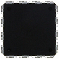
MCF5307AI90B Freescale Semiconductor, MCF5307AI90B Datasheet - Page 425

MCF5307AI90B
Manufacturer Part Number
MCF5307AI90B
Description
IC MPU 32BIT COLDF 90MHZ 208FQFP
Manufacturer
Freescale Semiconductor
Series
MCF530xr
Datasheets
1.MCF5307AI66B.pdf
(484 pages)
2.MCF5307AI66B.pdf
(16 pages)
3.MCF5307AI66B.pdf
(2 pages)
Specifications of MCF5307AI90B
Core Processor
Coldfire V3
Core Size
32-Bit
Speed
90MHz
Connectivity
EBI/EMI, I²C, UART/USART
Peripherals
DMA, POR, WDT
Number Of I /o
16
Program Memory Type
ROMless
Ram Size
4K x 8
Voltage - Supply (vcc/vdd)
3 V ~ 3.6 V
Oscillator Type
External
Operating Temperature
0°C ~ 70°C
Package / Case
208-FQFP
Maximum Clock Frequency
90 MHz
Maximum Operating Temperature
+ 105 C
Mounting Style
SMD/SMT
Minimum Operating Temperature
0 C
Family Name
MCF5xxx
Device Core
ColdFire
Device Core Size
32b
Frequency (max)
90MHz
Instruction Set Architecture
RISC
Supply Voltage 1 (typ)
3.3V
Operating Temp Range
0C to 70C
Operating Temperature Classification
Commercial
Mounting
Surface Mount
Pin Count
208
Package Type
FQFP
Program Memory Size
8KB
Cpu Speed
90MHz
Embedded Interface Type
I2C, UART
Digital Ic Case Style
FQFP
No. Of Pins
208
Supply Voltage Range
3V To 3.6V
Rohs Compliant
Yes
Lead Free Status / RoHS Status
Lead free / RoHS Compliant
Eeprom Size
-
Program Memory Size
-
Data Converters
-
Lead Free Status / Rohs Status
Lead free / RoHS Compliant
Available stocks
Company
Part Number
Manufacturer
Quantity
Price
Company:
Part Number:
MCF5307AI90B
Manufacturer:
FREESCAL
Quantity:
153
Company:
Part Number:
MCF5307AI90B
Manufacturer:
Freescale Semiconductor
Quantity:
10 000
Part Number:
MCF5307AI90B
Manufacturer:
FREESCALE
Quantity:
20 000
- Current page: 425 of 484
- Download datasheet (6Mb)
Chapter 19
IEEE 1149.1 Test Access Port (JTAG)
This chapter describes configuration and operation of the MCF5307 JTAG test
implementation. It describes the use of JTAG instructions and provides information on how
to disable JTAG functionality.
19.1 Overview
The MCF5307 dedicated user-accessible test logic is fully compliant with the publication
Standard Test Access Port and Boundary-Scan Architecture, IEEE Standard 1149.1. Use the
following description in conjunction with the supporting IEEE document listed above. This
section includes the description of those chip-specific items that the IEEE standard requires
as well as those items specific to the MCF5307 implementation.
The MCF5307 JTAG test architecture supports circuit board test strategies based on the
IEEE standard. This architecture provides access to all data and chip control pins from the
board-edge connector through the standard four-pin test access port (TAP) and the JTAG
reset pin, TRST. Test logic design is static and is independent of the system logic except
where the JTAG is subordinate to other complimentary test modes, as described in
Chapter 5, “Debug Support.” When in subordinate mode, JTAG test logic is placed in reset
and the TAP pins can be used for other purposes, as described in Table 19-1.
The MCF5307 JTAG implementation can do the following:
• Perform boundary-scan operations to test circuit board electrical continuity
• Bypass the MCF5307 by reducing the shift register path to a single cell
• Set MCF5307 output drive pins to fixed logic values while reducing the shift register
• Sample MCF5307 system pins during operation and transparently shift out the result
• Protect MCF5307 system output and input pins from backdriving and random
path to a single cell
toggling (such as during in-circuit testing) by placing all system pins in high-
impedance state
IEEE Standard 1149.1 may interfere with system designs that do
not incorporate JTAG capability. Section 19.6, “Disabling IEEE
Standard 1149.1 Operation,” describes precautions for ensuring
that this logic does not affect system or debug operation.
Chapter 19. IEEE 1149.1 Test Access Port (JTAG)
Freescale Semiconductor, Inc.
For More Information On This Product,
Go to: www.freescale.com
NOTE:
19-1
Related parts for MCF5307AI90B
Image
Part Number
Description
Manufacturer
Datasheet
Request
R
Part Number:
Description:
Manufacturer:
Freescale Semiconductor, Inc
Datasheet:
Part Number:
Description:
Mcf5307 Coldfire Integrated Microprocessor User
Manufacturer:
Freescale Semiconductor, Inc
Datasheet:
Part Number:
Description:
Manufacturer:
Freescale Semiconductor, Inc
Datasheet:
Part Number:
Description:
Manufacturer:
Freescale Semiconductor, Inc
Datasheet:
Part Number:
Description:
Manufacturer:
Freescale Semiconductor, Inc
Datasheet:
Part Number:
Description:
Manufacturer:
Freescale Semiconductor, Inc
Datasheet:
Part Number:
Description:
Manufacturer:
Freescale Semiconductor, Inc
Datasheet:
Part Number:
Description:
Manufacturer:
Freescale Semiconductor, Inc
Datasheet:
Part Number:
Description:
Manufacturer:
Freescale Semiconductor, Inc
Datasheet:
Part Number:
Description:
Manufacturer:
Freescale Semiconductor, Inc
Datasheet:
Part Number:
Description:
Manufacturer:
Freescale Semiconductor, Inc
Datasheet:
Part Number:
Description:
Manufacturer:
Freescale Semiconductor, Inc
Datasheet:
Part Number:
Description:
Manufacturer:
Freescale Semiconductor, Inc
Datasheet:
Part Number:
Description:
Manufacturer:
Freescale Semiconductor, Inc
Datasheet:
Part Number:
Description:
Manufacturer:
Freescale Semiconductor, Inc
Datasheet:


