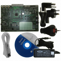
EVB9S12XEP100 Freescale Semiconductor, EVB9S12XEP100 Datasheet - Page 204

EVB9S12XEP100
Manufacturer Part Number
EVB9S12XEP100
Description
BOARD EVAL FOR MC9S12XEP100
Manufacturer
Freescale Semiconductor
Type
MCUr
Datasheet
1.EVB9S12XEP100.pdf
(1328 pages)
Specifications of EVB9S12XEP100
Contents
Module and Misc Hardware
Processor To Be Evaluated
MC9S12XEP100
Data Bus Width
16 bit
Interface Type
RS-232
Silicon Manufacturer
Freescale
Core Architecture
S12
Core Sub-architecture
S12
Silicon Core Number
MC9S12
Silicon Family Name
S12XE
Rohs Compliant
Yes
For Use With/related Products
MC9S12XEP100
Lead Free Status / RoHS Status
Lead free / RoHS Compliant
- Current page: 204 of 1328
- Download datasheet (9Mb)
Chapter 3 Memory Mapping Control (S12XMMCV4)
EROMON and ROMON control the visibility of the Flash in the memory map for CPU or BDM (not for
XGATE). Both local and global memory maps are affected.
204
Because of an order from the United States International Trade Commission, BGA-packaged product lines and partnumbers
EROMON
ROMHM
ROMON
indicated here currently are not available from Freescale for import or sale in the United States prior to September 2010
Field
2
1
0
1. Internal Flash means Flash resources inside the MCU are read/written.
2. The external access stretch mechanism is part of the EBI module (refer to EBI Block Guide for details).
Emulation memory means resources inside the emulator are read/written (PRU registers, flash
replacement, RAM, EEPROM and register space are always considered internal).
External application means resources residing outside the MCU are read/written.
Emulation Single Chip
Emulation Expanded
Enables emulated Flash or ROM memory in the memory map
Write: Never
This bit is used in some modes to define the placement of the Emulated Flash or ROM (Refer to
0 Disables the emulated Flash or ROM in the memory map.
1 Enables the emulated Flash or ROM in the memory map.
FLASH or ROM only in higher Half of Memory Map
Write: Once in normal and emulation modes and anytime in special modes
0 The fixed page of Flash or ROM can be accessed in the lower half of the memory map. Accesses to
1 Disables access to the Flash or ROM in the lower half of the memory map.These physical locations of the
Enable FLASH or ROM in the memory map
Write: Once in normal and emulation modes and anytime in special modes.
This bit is used in some modes to define the placement of the ROM (Refer to
0 Disables the Flash or ROM from the memory map.
1 Enables the Flash or ROM in the memory map.
Normal Single Chip
Special Single Chip
Normal Expanded
0x4000–0x7FFF will be mapped to 0x7F_4000-0x7F_7FFF in the global memory space.
Flash or ROM can still be accessed through the program page window. Accesses to 0x4000–0x7FFF will be
mapped to 0x14_4000-0x14_7FFF in the global memory space (external access).
Chip Modes
Special Test
Table 3-12. Data Sources when CPU or BDM is Accessing Flash Area
Table 3-11. MMCCTL1 Field Descriptions (continued)
MC9S12XE-Family Reference Manual , Rev. 1.23
ROMON
X
X
X
0
1
0
1
1
0
1
EROMON
X
X
X
X
X
X
0
1
0
1
Description
External Application
External Application
External Application
Emulation Memory
Emulation Memory
DATA SOURCE
Internal Flash
Internal Flash
Internal Flash
Internal Flash
Internal Flash
Table
(1)
3-12)
Freescale Semiconductor
Stretch
N
N
Y
N
Y
N
N
Table
(2)
3-12)
Related parts for EVB9S12XEP100
Image
Part Number
Description
Manufacturer
Datasheet
Request
R
Part Number:
Description:
Manufacturer:
Freescale Semiconductor, Inc
Datasheet:
Part Number:
Description:
Manufacturer:
Freescale Semiconductor, Inc
Datasheet:
Part Number:
Description:
Manufacturer:
Freescale Semiconductor, Inc
Datasheet:
Part Number:
Description:
Manufacturer:
Freescale Semiconductor, Inc
Datasheet:
Part Number:
Description:
Manufacturer:
Freescale Semiconductor, Inc
Datasheet:
Part Number:
Description:
Manufacturer:
Freescale Semiconductor, Inc
Datasheet:
Part Number:
Description:
Manufacturer:
Freescale Semiconductor, Inc
Datasheet:
Part Number:
Description:
Manufacturer:
Freescale Semiconductor, Inc
Datasheet:
Part Number:
Description:
Manufacturer:
Freescale Semiconductor, Inc
Datasheet:
Part Number:
Description:
Manufacturer:
Freescale Semiconductor, Inc
Datasheet:
Part Number:
Description:
Manufacturer:
Freescale Semiconductor, Inc
Datasheet:
Part Number:
Description:
Manufacturer:
Freescale Semiconductor, Inc
Datasheet:
Part Number:
Description:
Manufacturer:
Freescale Semiconductor, Inc
Datasheet:
Part Number:
Description:
Manufacturer:
Freescale Semiconductor, Inc
Datasheet:
Part Number:
Description:
Manufacturer:
Freescale Semiconductor, Inc
Datasheet:


