EVB9S12XEP100 Freescale Semiconductor, EVB9S12XEP100 Datasheet - Page 717
EVB9S12XEP100
Manufacturer Part Number
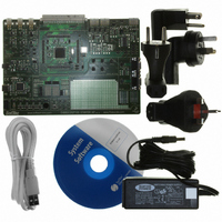
EVB9S12XEP100
Description
BOARD EVAL FOR MC9S12XEP100
Manufacturer
Freescale Semiconductor
Type
MCUr
Datasheet
1.EVB9S12XEP100.pdf
(1328 pages)
Specifications of EVB9S12XEP100
Contents
Module and Misc Hardware
Processor To Be Evaluated
MC9S12XEP100
Data Bus Width
16 bit
Interface Type
RS-232
Silicon Manufacturer
Freescale
Core Architecture
S12
Core Sub-architecture
S12
Silicon Core Number
MC9S12
Silicon Family Name
S12XE
Rohs Compliant
Yes
For Use With/related Products
MC9S12XEP100
Lead Free Status / RoHS Status
Lead free / RoHS Compliant


channel becomes enabled (PWMEx = 1), the associated PWM counter continues from the count in the
PWMCNTx register. This allows the waveform to continue where it left off when the channel is re-
enabled. When the channel is disabled, writing “0” to the period register will cause the counter to reset on
the next selected clock.
Generally, writes to the counter are done prior to enabling a channel in order to start from a known state.
However, writing a counter can also be done while the PWM channel is enabled (counting). The effect is
similar to writing the counter when the channel is disabled, except that the new period is started
immediately with the output set according to the polarity bit.
The counter is cleared at the end of the effective period (see
Section 19.4.2.6, “Center Aligned Outputs”
19.4.2.5
The PWM timer provides the choice of two types of outputs, left aligned or center aligned. They are
selected with the CAEx bits in the PWMCAE register. If the CAEx bit is cleared (CAEx = 0), the
corresponding PWM output will be left aligned.
In left aligned output mode, the 8-bit counter is configured as an up counter only. It compares to two
registers, a duty register and a period register as shown in the block diagram in
PWM counter matches the duty register the output flip-flop changes state causing the PWM waveform to
also change state. A match between the PWM counter and the period register resets the counter and the
output flip-flop, as shown in
duty register to the associated registers, as described in
counter counts from 0 to the value in the period register – 1.
Freescale Semiconductor
Because of an order from the United States International Trade Commission, BGA-packaged product lines and partnumbers
When PWMCNTx register written to
indicated here currently are not available from Freescale for import or sale in the United States prior to September 2010
Counter Clears ($00)
Effective period ends
any value
Left Aligned Outputs
If the user wants to start a new “clean” PWM waveform without any
“history” from the old waveform, the user must write to channel counter
(PWMCNTx) prior to enabling the PWM channel (PWMEx = 1).
Writing to the counter while the channel is enabled can cause an irregular
PWM cycle to occur.
Changing the PWM output mode from left aligned to center aligned output
(or vice versa) while channels are operating can cause irregularities in the
PWM output. It is recommended to program the output mode before
enabling the PWM channel.
Figure
Table 19-4. PWM Timer Counter Conditions
MC9S12XE-Family Reference Manual Rev. 1.23
19-19, as well as performing a load from the double buffer period and
(PWMEx = 1). Counts from last value in
When PWM channel is enabled
for more details).
Counter Counts
PWMCNTx.
NOTE
NOTE
NOTE
Section 19.4.2.3, “PWM Period and
Section 19.4.2.5, “Left Aligned Outputs”
Chapter 19 Pulse-Width Modulator (S12PWM8B8CV1)
When PWM channel is disabled
Figure
Counter Stops
(PWMEx = 0)
19-19. When the
Duty”. The
and
717
Related parts for EVB9S12XEP100
Image
Part Number
Description
Manufacturer
Datasheet
Request
R

Part Number:
Description:
Manufacturer:
Freescale Semiconductor, Inc
Datasheet:
Part Number:
Description:
Manufacturer:
Freescale Semiconductor, Inc
Datasheet:
Part Number:
Description:
Manufacturer:
Freescale Semiconductor, Inc
Datasheet:
Part Number:
Description:
Manufacturer:
Freescale Semiconductor, Inc
Datasheet:
Part Number:
Description:
Manufacturer:
Freescale Semiconductor, Inc
Datasheet:
Part Number:
Description:
Manufacturer:
Freescale Semiconductor, Inc
Datasheet:
Part Number:
Description:
Manufacturer:
Freescale Semiconductor, Inc
Datasheet:
Part Number:
Description:
Manufacturer:
Freescale Semiconductor, Inc
Datasheet:
Part Number:
Description:
Manufacturer:
Freescale Semiconductor, Inc
Datasheet:
Part Number:
Description:
Manufacturer:
Freescale Semiconductor, Inc
Datasheet:
Part Number:
Description:
Manufacturer:
Freescale Semiconductor, Inc
Datasheet:
Part Number:
Description:
Manufacturer:
Freescale Semiconductor, Inc
Datasheet:
Part Number:
Description:
Manufacturer:
Freescale Semiconductor, Inc
Datasheet:
Part Number:
Description:
Manufacturer:
Freescale Semiconductor, Inc
Datasheet:
Part Number:
Description:
Manufacturer:
Freescale Semiconductor, Inc
Datasheet: