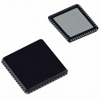
ADUC847BCPZ8-5 Analog Devices Inc, ADUC847BCPZ8-5 Datasheet - Page 57

ADUC847BCPZ8-5
Manufacturer Part Number
ADUC847BCPZ8-5
Description
IC,Data Acquisition CODEC,2-CHANNEL,LLCC,56PIN,PLASTIC
Manufacturer
Analog Devices Inc
Series
MicroConverter® ADuC8xxr
Datasheet
1.EVAL-ADUC845QSZ.pdf
(108 pages)
Specifications of ADUC847BCPZ8-5
Core Processor
8052
Core Size
8-Bit
Speed
12.58MHz
Connectivity
I²C, SPI, UART/USART
Peripherals
POR, PSM, PWM, Temp Sensor, WDT
Number Of I /o
34
Program Memory Size
8KB (8K x 8)
Program Memory Type
FLASH
Eeprom Size
4K x 8
Ram Size
2.25K x 8
Voltage - Supply (vcc/vdd)
4.75 V ~ 5.25 V
Data Converters
A/D 10x24b; D/A 1x12b, 2x16b
Oscillator Type
Internal
Operating Temperature
-40°C ~ 85°C
Package / Case
56-LFCSP
Lead Free Status / RoHS Status
Lead free / RoHS Compliant
For Use With
EVAL-ADUC847QSZ - KIT DEV QUICK START FOR ADUC847
Lead Free Status / RoHS Status
Lead free / RoHS Compliant
PWM Cycle Width High Byte (PWM1H)
SFR Address:
Power-On Default:
Bit Addressable:
Table 37. PWM1H: PWM Cycle Width High Byte
PWM1H.7
0
R/W
PWM Cycle Width Low Byte (PWM1L)
SFR Address:
Power-On Default:
Bit Addressable:
Table 38. PWM1L: PWM Cycle Width Low Byte
PWM1L.7
0
R/W
Mode 0
In Mode 0, the PWM is disabled, allowing P2.5 and P2.6 to be
used as normal digital I/Os.
Mode 1 (Single-Variable Resolution PWM)
In Mode 1, both the pulse length and the cycle time (period) are
programmable in user code, allowing the resolution of the PWM
to be variable. PWM1H/L sets the period of the output waveform.
Reducing PWM1H/L reduces the resolution of the PWM output
but increases the maximum output rate of the PWM. For
example, setting PWM1H/L to 65536 gives a 16-bit PWM with
a maximum output rate of 192 Hz (12.583 MHz/65536). Setting
PWM1H/L to 4096 gives a 12-bit PWM with a maximum
output rate of 3072 Hz (12.583 MHz/4096).
PWM0H/L sets the duty cycle of the PWM output waveform as
shown in Figure 39.
PWM1H.6
0
R/W
PWM1L.6
0
R/W
PWM COUNTER
Figure 39. PWM in Mode 1
B4H
00H
No
B3H
00H
No
PWM1H.5
0
R/W
PWM1L.5
0
R/W
PWM1H/L
PWM0H/L
P2.5
0
PWM1H.4
0
R/W
PWM1L.4
0
R/W
Rev. B | Page 57 of 108
PWM1H.3
0
R/W
PWM1L.3
0
R/W
Mode 2 (Twin 8-Bit PWM)
In Mode 2, the duty cycle and the resolution of the PWM
outputs are programmable. The maximum resolution of the
PWM output is 8 bits.
PWM1L sets the period for both PWM outputs. Typically, this
is set to 255 (FFH) to give an 8-bit PWM, although it is possible
to reduce this as necessary. A value of 100 could be loaded here
to give a percentage PWM, that is, the PWM is accurate to 1%.
The outputs of the PWM at P2.5 and P2.6 are shown in Figure 40.
As can be seen, the output of PWM0 (P2.5) goes low when the
PWM counter equals PWM0L. The output of PWM1 (P2.6) goes
high when the PWM counter equals PWM1H and goes low
again when the PWM counter equals PWM0H. Setting PWM1H
to 0 ensures that both PWM outputs start simultaneously.
PWM1H.2
0
R/W
PWM1L.2
0
R/W
PWM COUNTER
ADuC845/ADuC847/ADuC848
Figure 40. PWM Mode 2
PWM1H.1
0
R/W
PWM1L.1
0
R/W
PWM1H.0
0
R/W
PWM1L.0
0
R/W
PWM1L
PWM0H
PWM0L
PWM1H
P2.5
P2.6
0


