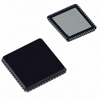
ADUC847BCPZ8-5 Analog Devices Inc, ADUC847BCPZ8-5 Datasheet - Page 78

ADUC847BCPZ8-5
Manufacturer Part Number
ADUC847BCPZ8-5
Description
IC,Data Acquisition CODEC,2-CHANNEL,LLCC,56PIN,PLASTIC
Manufacturer
Analog Devices Inc
Series
MicroConverter® ADuC8xxr
Datasheet
1.EVAL-ADUC845QSZ.pdf
(108 pages)
Specifications of ADUC847BCPZ8-5
Core Processor
8052
Core Size
8-Bit
Speed
12.58MHz
Connectivity
I²C, SPI, UART/USART
Peripherals
POR, PSM, PWM, Temp Sensor, WDT
Number Of I /o
34
Program Memory Size
8KB (8K x 8)
Program Memory Type
FLASH
Eeprom Size
4K x 8
Ram Size
2.25K x 8
Voltage - Supply (vcc/vdd)
4.75 V ~ 5.25 V
Data Converters
A/D 10x24b; D/A 1x12b, 2x16b
Oscillator Type
Internal
Operating Temperature
-40°C ~ 85°C
Package / Case
56-LFCSP
Lead Free Status / RoHS Status
Lead free / RoHS Compliant
For Use With
EVAL-ADUC847QSZ - KIT DEV QUICK START FOR ADUC847
Lead Free Status / RoHS Status
Lead free / RoHS Compliant
ADuC845/ADuC847/ADuC848
T2CON—Timer/Counter 2 Control Register
SFR Address:
Power-On Default:
Bit Addressable:
Table 52. T2CON SFR Bit Designations
Bit No.
7
6
5
4
3
2
1
0
Timer/Counter 2 Data Registers
Timer/Counter 2 also has two pairs of 8-bit data registers
associated with it. These are used as both timer data registers
and as timer capture/reload registers.
TH2 and TL2—Timer 2 data high byte and low byte.
SFR Address:
Power-On Default:
RCAP2H and RCAP2L—Timer 2 capture/reload byte and low
SFR Address:
Power-On Default:
Name
TF2
EXF2
RCLK
TCLK
EXEN2
TR2
CNT2
CAP2
Description
Timer 2 Overflow Flag.
Set by hardware on a Timer 2 overflow. TF2 cannot be set when either RCLK = 1 or TCLK = 1.
Cleared by user software.
Timer 2 External Flag.
Set by hardware when either a capture or reload is caused by a negative transition on T2EX and EXEN2 = 1.
Cleared by user software.
Receive Clock Enable Bit.
Set by the user to enable the serial port to use Timer 2 overflow pulses for its receive clock in serial port Modes 1 and 3.
Cleared by the user to enable Timer 1 overflow to be used for the receive clock.
Transmit Clock Enable Bit.
Set by the user to enable the serial port to use Timer 2 overflow pulses for its transmit clock in serial port Modes 1 and 3.
Cleared by the user to enable Timer 1 overflow to be used for the transmit clock.
Timer 2 External Enable Flag.
Set by the user to enable a capture or reload to occur as a result of a negative transition on T2EX if Timer 2 is not being
used to clock the serial port.
Cleared by the user for Timer 2 to ignore events at T2EX.
Timer 2 Start/Stop Control Bit.
Set by the user to start Timer 2.
Cleared by the user to stop Timer 2.
Timer 2 Timer or Counter Function Select Bit.
Set by the user to select the counter function (input from external T2 pin).
Cleared by the user to select the timer function (input from on-chip core clock).
Timer 2 Capture/Reload Select Bit.
Set by the user to enable captures on negative transitions at T2EX if EXEN2 = 1.
Cleared by the user to enable autoreloads with Timer 2 overflows or negative transitions at T2EX when EXEN2 = 1.
When either RCLK = 1 or TCLK = 1, this bit is ignored and the timer is forced to autoreload on Timer 2 overflow.
C8H
00H
Yes
CDH and CCH respectively.
00H and 00H, respectively.
CBH and CAH, respectively.
00H and 00H, respectively.
byte.
Rev. B | Page 78 of 108


