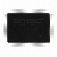
LAN91C111I-NS SMSC, LAN91C111I-NS Datasheet - Page 103

LAN91C111I-NS
Manufacturer Part Number
LAN91C111I-NS
Description
IC ETHERNET CTLR MAC PHY 128-QFP
Manufacturer
SMSC
Type
Single Chip MAC and PHYr
Datasheet
1.LAN91C111-NU.pdf
(128 pages)
Specifications of LAN91C111I-NS
Controller Type
Ethernet Controller, MAC/PHY
Interface
Serial EEPROM
Voltage - Supply
3.3V
Operating Temperature
-40°C ~ 85°C
Mounting Type
Surface Mount
Package / Case
128-QFP
Product
Ethernet Controllers
Number Of Transceivers
1
Standard Supported
IEEE 802.3 or IEEE 802.3u
Data Rate
10 Mbps or 100 Mbps
Supply Voltage (max)
5 V
Supply Voltage (min)
0 V
Supply Current (max)
140 mA
Maximum Operating Temperature
+ 85 C
Ethernet Connection Type
100BASE-T or 100BASE-T4 or 100BASE-TX or 10BASE-T
Minimum Operating Temperature
- 40 C
Mounting Style
SMD/SMT
Lead Free Status / RoHS Status
Lead free / RoHS Compliant
Current - Supply
-
Lead Free Status / Rohs Status
Lead free / RoHS Compliant
Other names
638-1014
Available stocks
Company
Part Number
Manufacturer
Quantity
Price
Company:
Part Number:
LAN91C111I-NS
Manufacturer:
RECOM
Quantity:
1 000
Company:
Part Number:
LAN91C111I-NS
Manufacturer:
SMSC
Quantity:
1 000
Company:
Part Number:
LAN91C111I-NS
Manufacturer:
Standard
Quantity:
6 916
Company:
Part Number:
LAN91C111I-NS
Manufacturer:
Microchip Technology
Quantity:
10 000
10/100 Non-PCI Ethernet Single Chip MAC + PHY
Datasheet
SMSC LAN91C111 REV C
EISA BUS
SIGNAL
Latched W-R
combined with
nCMD
Latched W-R
combined with
nCMD
nSTART
RESDRV
nBE0 nBE1 nBE2
nBE3
IRQn
D0-D31
nEX32
nNOWS
(optional additional
logic)
THE FOLLOWING SIGNALS SUPPORT SLAVE DMA TYPE "C" BURST CYCLES
BCLK
nDAK<n>
nIORC
nIOWC
nEXRDY
UNUSED PINS
VCC
LAN91C111
SIGNAL
nRD
nWR
nADS
RESET
nBE0 n BE1 nBE2
nBE3
INTR0
D0-D31
nLDEV
LCLK
nDATACS
W/nR
nCYCLE
nRDYRTN
nVLBUS
Table 12.3 EISA 32 Bit Slave Signal Connections (continued)
NOTES
I/O Read strobe - asynchronous read accesses. Address is valid
before its leading edge. Must not be active during DMA bursts if
DMA is supported.
I/O Write strobe - asynchronous write access. Address is valid
before leading edge . Data latched on trailing edge. Must not be
active during DMA bursts if DMA is supported.
Address strobe is connected to EISA nSTART.
Byte enables. Latched on nADS rising edge.
Interrupts used as active high edge triggered
32 bit data bus. The bus byte(s) used to access the device are a
function of nBE0-nBE3:
Not used = tri-state on reads, ignored on writes. Note that nBE2 and
nBE3 override the value of A1, which is tied low in this application.
Other combinations of nBE are not supported by the LAN91C111.
Software drivers are not anticipated to generate them.
nLDEV is a totem pole output. nLDEV is active on valid decodes of
LAN91C111 pins A15-A4, and AEN=0. nNOWS is similar to nLDEV
except that it should go inactive on nSTART rising. nNOWS can be
used to request compressed cycles (1.5 BCLK long, nRD/nWR will
be 1/2 BCLK wide).
EISA Bus Clock. Data transfer clock for DMA bursts.
DMA Acknowledge. Active during Slave DMA cycles. Used by the
LAN91C111 as nDATACS direct access to data path.
Indicates the direction and timing of the DMA cycles. High during
LAN91C111 writes, low during LAN91C111 reads.
Indicates slave DMA writes.
EISA bus signal indicating whether a slave DMA cycle will take place
on the next BCLK rising edge, or should be postponed. nRDYRTN
is used as an input in the slave DMA mode to bring in EXRDY.
nBE0
DATASHEET
0
0
1
0
1
1
1
103
nBE1
0
0
1
1
0
1
1
nBE2
0
0
1
1
1
0
1
nBE3
0
1
0
1
1
1
0
Double word access
High word access
Low word access
Byte 0 access
Byte 1 access
Byte 2 access
Byte 3 access
Revision 1.91 (06-01-09)


