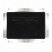
LAN91C111I-NS SMSC, LAN91C111I-NS Datasheet - Page 54

LAN91C111I-NS
Manufacturer Part Number
LAN91C111I-NS
Description
IC ETHERNET CTLR MAC PHY 128-QFP
Manufacturer
SMSC
Type
Single Chip MAC and PHYr
Datasheet
1.LAN91C111-NU.pdf
(128 pages)
Specifications of LAN91C111I-NS
Controller Type
Ethernet Controller, MAC/PHY
Interface
Serial EEPROM
Voltage - Supply
3.3V
Operating Temperature
-40°C ~ 85°C
Mounting Type
Surface Mount
Package / Case
128-QFP
Product
Ethernet Controllers
Number Of Transceivers
1
Standard Supported
IEEE 802.3 or IEEE 802.3u
Data Rate
10 Mbps or 100 Mbps
Supply Voltage (max)
5 V
Supply Voltage (min)
0 V
Supply Current (max)
140 mA
Maximum Operating Temperature
+ 85 C
Ethernet Connection Type
100BASE-T or 100BASE-T4 or 100BASE-TX or 10BASE-T
Minimum Operating Temperature
- 40 C
Mounting Style
SMD/SMT
Lead Free Status / RoHS Status
Lead free / RoHS Compliant
Current - Supply
-
Lead Free Status / Rohs Status
Lead free / RoHS Compliant
Other names
638-1014
Available stocks
Company
Part Number
Manufacturer
Quantity
Price
Company:
Part Number:
LAN91C111I-NS
Manufacturer:
RECOM
Quantity:
1 000
Company:
Part Number:
LAN91C111I-NS
Manufacturer:
SMSC
Quantity:
1 000
Company:
Part Number:
LAN91C111I-NS
Manufacturer:
Standard
Quantity:
6 916
Company:
Part Number:
LAN91C111I-NS
Manufacturer:
Microchip Technology
Quantity:
10 000
Revision 1.91 (06-01-09)
8.11
BYTE
BYTE
HIGH
LOW
Bank 1 - Configuration Register
Reserved
Reserved – Must be 0.
The Configuration Register holds bits that define the adapter configuration and are not expected to
change during run-time. This register is part of the EEPROM saved setup.
EPH Power EN - Used to selectively power transition the EPH to a low power mode. When this bit is
cleared (0), the Host will place the EPH into a low power mode. The Ethernet MAC will gate the 25Mhz
TX and RX clock so that the Ethernet MAC will no longer be able to receive and transmit packets. The
Host interface however, will still be active allowing the Host access to the device through Standard IO
access. All LAN91C111 registers will still be accessible. However, status and control will not be allowed
until the EPH Power EN bit is set AND a RESET MMU command is initiated.
NO WAIT - When set, does not request additional wait states. An exception to this are accesses to
the Data Register if not ready for a transfer. When clear, negates ARDY for two to three clocks on
any cycle to the LAN91C111.
GPCNTRL - This bit is a general purpose output port. Its inverse value drives pin nCNTRL and it is
typically connected to a SELECT pin of the external PHY device such as a power enable. It can be
used to select the signaling mode for the external PHY or as a general purpose non-volatile
configuration pin. Defaults low.
EXT PHY – External PHY Enabled.
This bit, when set (1):
a. Enables the external MII.
b. The Internal PHY is disabled and is disconnected (Tri-stated from the internal MII along with any
When this bit is cleared (0 - Default):
a. The internal PHY is enabled.
b. The external MII pins, including the MII Management interface pins are tri-stated.
Reserved – Reserved bits.
Power
EPH
EN
sideband signals (such as MDINT) going to the MAC Core).
1
1
OFFSET
0
Reserved
Reserved
0
0
CONFIGURATION
Reserved
REGISTER
NAME
1
1
DATASHEET
Reserved
WAIT
NO
0
1
54
Reserved
READ/WRITE
0
0
TYPE
10/100 Non-PCI Ethernet Single Chip MAC + PHY
GPCNTRL
Reserved
0
0
SYMBOL
CR
EXT PHY
Reserved
SMSC LAN91C111 REV C
0
0
Reserved
Reserved
Datasheet
0
1


