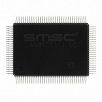
LAN91C111I-NS SMSC, LAN91C111I-NS Datasheet - Page 85

LAN91C111I-NS
Manufacturer Part Number
LAN91C111I-NS
Description
IC ETHERNET CTLR MAC PHY 128-QFP
Manufacturer
SMSC
Type
Single Chip MAC and PHYr
Datasheet
1.LAN91C111-NU.pdf
(128 pages)
Specifications of LAN91C111I-NS
Controller Type
Ethernet Controller, MAC/PHY
Interface
Serial EEPROM
Voltage - Supply
3.3V
Operating Temperature
-40°C ~ 85°C
Mounting Type
Surface Mount
Package / Case
128-QFP
Product
Ethernet Controllers
Number Of Transceivers
1
Standard Supported
IEEE 802.3 or IEEE 802.3u
Data Rate
10 Mbps or 100 Mbps
Supply Voltage (max)
5 V
Supply Voltage (min)
0 V
Supply Current (max)
140 mA
Maximum Operating Temperature
+ 85 C
Ethernet Connection Type
100BASE-T or 100BASE-T4 or 100BASE-TX or 10BASE-T
Minimum Operating Temperature
- 40 C
Mounting Style
SMD/SMT
Lead Free Status / RoHS Status
Lead free / RoHS Compliant
Current - Supply
-
Lead Free Status / Rohs Status
Lead free / RoHS Compliant
Other names
638-1014
Available stocks
Company
Part Number
Manufacturer
Quantity
Price
Company:
Part Number:
LAN91C111I-NS
Manufacturer:
RECOM
Quantity:
1 000
Company:
Part Number:
LAN91C111I-NS
Manufacturer:
SMSC
Quantity:
1 000
Company:
Part Number:
LAN91C111I-NS
Manufacturer:
Standard
Quantity:
6 916
Company:
Part Number:
LAN91C111I-NS
Manufacturer:
Microchip Technology
Quantity:
10 000
10/100 Non-PCI Ethernet Single Chip MAC + PHY
Datasheet
SMSC LAN91C111 REV C
10.2
1
2
3
4
5
1
2
3
4
5
6
7
8
9
S/W DRIVER
ISSUE ALLOCATE MEMORY FOR TX - N BYTES -
the MMU attempts to allocate N bytes of RAM.
WAIT FOR SUCCESSFUL COMPLETION CODE -
Poll until the ALLOC INT bit is set or enable its mask
bit and wait for the interrupt. The TX packet number
is now at the Allocation Result Register.
LOAD TRANSMIT DATA - Copy the TX packet
number into the Packet Number Register. Write the
Pointer Register, then use a block move operation
from the upper layer transmit queue into the Data
Register.
ISSUE "ENQUEUE PACKET NUMBER TO TX FIFO"
- This command writes the number present in the
Packet Number Register into the TX FIFO. The
transmission is now enqueued. No further CPU
intervention is needed until a transmit interrupt is
generated.
S/W DRIVER
Write and set (1) the “EPH Power EN” Bit, located in
the configuration register, Bank 1 Offset 0.
Write the PDN bit in PHY MI Register 0 to 0
Issue MMU Reset Command
Restore Device Register Level Context.
Enable Transmitter – Set the TXENA bit of the
Transmit Control Register
Enable Receiver – Set (1) the RXEN bit of the
Receive Control Register.
Typical Flow of Events for Transmit (Auto Release = 0)
Table 10.2 Flow Of Events For Restoring Device In Normal Power Mode
DATASHEET
85
MAC SIDE
The enqueued packet will be transferred to the MAC
block as a function of TXENA (nTCR) bit and of the
deferral process (1/2 duplex mode only) state.
CONTROLLER FUNCTION
Ethernet MAC Enables the RX Clock, TX clock
derived from the Internal PHY. The EPH Clock is
also enabled.
The PHY is then set in isolation mode (MII_DIS bit
is set). Need to clear this MII_DIS bit; and, need to
wait for 500 ms for the PHY to restore normal.
Internal PHY entered normal operation mode
Ethernet MAC can now transmit Ethernet Packets.
Ethernet MAC is now able to receive Packets.
Ethernet MAC is now restored for normal operation.
Revision 1.91 (06-01-09)


