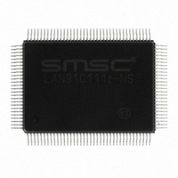
LAN91C111I-NS SMSC, LAN91C111I-NS Datasheet - Page 35

LAN91C111I-NS
Manufacturer Part Number
LAN91C111I-NS
Description
IC ETHERNET CTLR MAC PHY 128-QFP
Manufacturer
SMSC
Type
Single Chip MAC and PHYr
Datasheet
1.LAN91C111-NU.pdf
(128 pages)
Specifications of LAN91C111I-NS
Controller Type
Ethernet Controller, MAC/PHY
Interface
Serial EEPROM
Voltage - Supply
3.3V
Operating Temperature
-40°C ~ 85°C
Mounting Type
Surface Mount
Package / Case
128-QFP
Product
Ethernet Controllers
Number Of Transceivers
1
Standard Supported
IEEE 802.3 or IEEE 802.3u
Data Rate
10 Mbps or 100 Mbps
Supply Voltage (max)
5 V
Supply Voltage (min)
0 V
Supply Current (max)
140 mA
Maximum Operating Temperature
+ 85 C
Ethernet Connection Type
100BASE-T or 100BASE-T4 or 100BASE-TX or 10BASE-T
Minimum Operating Temperature
- 40 C
Mounting Style
SMD/SMT
Lead Free Status / RoHS Status
Lead free / RoHS Compliant
Current - Supply
-
Lead Free Status / Rohs Status
Lead free / RoHS Compliant
Other names
638-1014
Available stocks
Company
Part Number
Manufacturer
Quantity
Price
Company:
Part Number:
LAN91C111I-NS
Manufacturer:
RECOM
Quantity:
1 000
Company:
Part Number:
LAN91C111I-NS
Manufacturer:
SMSC
Quantity:
1 000
Company:
Part Number:
LAN91C111I-NS
Manufacturer:
Standard
Quantity:
6 916
Company:
Part Number:
LAN91C111I-NS
Manufacturer:
Microchip Technology
Quantity:
10 000
10/100 Non-PCI Ethernet Single Chip MAC + PHY
Datasheet
SMSC LAN91C111 REV C
7.7.9
7.7.10
Equalizer Disable
The adaptive equalizer can be disabled by setting the equalizer disable bit in the PHY Ml serial port
Configuration 1 register. When disabled, the equalizer is forced into the response it would normally
have if zero cable length was detected.
Receive Level Adjust
The receiver squelch and unsquelch levels can be lowered by 4.5 dB by setting the receive level adjust
bit in the PHY Ml serial port Configuration 1 register. By setting this bit, the device may be able to
support longer cable lengths.
Collision
100 Mbps
Collision occurs whenever transmit and receive occur simultaneously while the device is in Half
Duplex.
Collision is sensed whenever there is simultaneous transmission (packet transmission on TPO±) and
reception (non-idle symbols detected on TP input). When collision is detected, the MAC is notified.
Once collision starts, the receive and transmit packets that caused the collision are terminated by their
respective MACs until the responsible MACs terminate the transmission, the PHY continues to pass
the data on.
The collision function is disabled if the device is in the Full Duplex mode, is in the Link Fail State, or
if the device is in the diagnostic loopback mode.
10 Mbps
Collision in 10Mbps mode is identical to the 100Mbps mode except, (1) reception is determined by the
10Mbps squelch criteria, (2) data being passed to the MAC are forced to all 0's, (3) MAC is notified of
the collision when the SQE test is performed, (4) MAC is notified of the collision when the jabber
condition has been detected.
Collision Test
The MAC and PHY collision indication can be tested by setting the collision test register bit in the PHY
MI serial port Control register. When this bit is set, internal TXEN from the MAC is looped back onto
COL and the TP outputs are disabled.
Start of Packet
100 Mbps
Start of packet for 100 Mbps mode is indicated by a unique Start of Stream Delimiter (referred to as
SSD). The SSD pattern consists of the two /J/K/ 5B symbols inserted at the beginning of the packet
in place of the first two preamble symbols, as defined in IEEE 802.3 Clause 24.
The transmit SSD is generated by the 4B5B encoder and the /J/K/ symbols are inserted by the 4B5B
encoder at the beginning of the transmit data packet in place of the first two 5B symbols of the
preamble.
The receive pattern is detected by the 4B5B decoder by examining groups of 10 consecutive code bits
(two 5B words) from the descrambler. Between packets, the receiver will be detecting the idle pattern,
which is 5B /I/ symbols. While in the idle state, the MAC is notified that no data/invalid data is received.
If the receiver is in the idle state and 10 consecutive code bits from the receiver consist of the /J/K/
symbols, the start of packet is detected, data reception is begun, the MAC is notified that valid data is
received, and 5/5/ symbols are substituted in place of the /J/K/ symbols.
If the receiver is in the idle state and 10 consecutive code bits from the receiver consist of a pattern
that is neither /I/I/ nor /J/K/ symbols but contains at least 2 non contiguous 0's, then activity is detected
but the start of packet is considered to be faulty and a False Carrier Indication (also referred to as bad
DATASHEET
35
Revision 1.91 (06-01-09)


