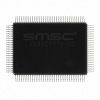
LAN91C111I-NS SMSC, LAN91C111I-NS Datasheet - Page 53

LAN91C111I-NS
Manufacturer Part Number
LAN91C111I-NS
Description
IC ETHERNET CTLR MAC PHY 128-QFP
Manufacturer
SMSC
Type
Single Chip MAC and PHYr
Datasheet
1.LAN91C111-NU.pdf
(128 pages)
Specifications of LAN91C111I-NS
Controller Type
Ethernet Controller, MAC/PHY
Interface
Serial EEPROM
Voltage - Supply
3.3V
Operating Temperature
-40°C ~ 85°C
Mounting Type
Surface Mount
Package / Case
128-QFP
Product
Ethernet Controllers
Number Of Transceivers
1
Standard Supported
IEEE 802.3 or IEEE 802.3u
Data Rate
10 Mbps or 100 Mbps
Supply Voltage (max)
5 V
Supply Voltage (min)
0 V
Supply Current (max)
140 mA
Maximum Operating Temperature
+ 85 C
Ethernet Connection Type
100BASE-T or 100BASE-T4 or 100BASE-TX or 10BASE-T
Minimum Operating Temperature
- 40 C
Mounting Style
SMD/SMT
Lead Free Status / RoHS Status
Lead free / RoHS Compliant
Current - Supply
-
Lead Free Status / Rohs Status
Lead free / RoHS Compliant
Other names
638-1014
Available stocks
Company
Part Number
Manufacturer
Quantity
Price
Company:
Part Number:
LAN91C111I-NS
Manufacturer:
RECOM
Quantity:
1 000
Company:
Part Number:
LAN91C111I-NS
Manufacturer:
SMSC
Quantity:
1 000
Company:
Part Number:
LAN91C111I-NS
Manufacturer:
Standard
Quantity:
6 916
Company:
Part Number:
LAN91C111I-NS
Manufacturer:
Microchip Technology
Quantity:
10 000
10/100 Non-PCI Ethernet Single Chip MAC + PHY
Datasheet
SMSC LAN91C111 REV C
LS2A
0
0
0
0
1
1
1
1
LS2B
0
0
0
0
1
1
1
1
WHAT DO YOU
WANT TO DO?
10 Half Duplex
10 Full Duplex
LS1A
0
0
1
1
0
0
1
1
LS1B
0
0
1
1
0
0
1
1
LS2A, LS1A, LS0A – LED select Signal Enable. These bits define what LED control signals are routed
to the LEDA output pin on the LAN91C111 Ethernet Controller. The default is 10/100 Link detected.
LS2B, LS1B, LS0B – LED select Signal Enable. These bits define what LED control signals are routed
to the LEDB output pin on the LAN91C111 Ethernet Controller. The default is 10/100 Link detected.
LS0A
0
1
0
1
0
1
0
1
LS0B
0
1
0
1
0
1
0
1
AUTO-NEGOTIATION
LED SELECT SIGNAL – LEDA
nPLED3+ nPLED0 – Logical OR of 100Mbps Link detected 10Mbps Link detected
(default)
Reserved
nPLED0 - 10Mbps Link detected
nPLED1 - Full Duplex Mode enabled
nPLED2 - Transmit or Receive packet occurred
nPLED3 - 100Mbps Link detected
nPLED4 - Receive packet occurred
nPLED5 - Transmit packet occurred
LED SELECT SIGNAL – LEDB
nPLED3+ nPLED0 – Logical OR of 100Mbps Link detected 10Mbps Link detected
(default)
Reserved
nPLED0 - 10Mbps Link detected
nPLED1 – Full Duplex Mode enabled
nPLED2 – Transmit or Receive packet occurred
nPLED3 - 100Mbps Link detected
nPLED4 - Receive packet occurred
nPLED5 - Transmit packet occurred
CONTROL BITS
0
0
1
0
0
1
0
1
0
0
1
0
DATASHEET
SPEED AND DUPLEX MODE CONTROL
0
X
0
X
0
0
53
FOR THE PHY
X
X
1
1
0
0
X
X
X
X
0
0
X
X
X
X
1
0
Revision 1.91 (06-01-09)
CONTROL
FOR THE
DUPLEX
MODE
MAC
1
1
1
0
0
0


