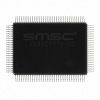
LAN91C111I-NS SMSC, LAN91C111I-NS Datasheet - Page 74

LAN91C111I-NS
Manufacturer Part Number
LAN91C111I-NS
Description
IC ETHERNET CTLR MAC PHY 128-QFP
Manufacturer
SMSC
Type
Single Chip MAC and PHYr
Datasheet
1.LAN91C111-NU.pdf
(128 pages)
Specifications of LAN91C111I-NS
Controller Type
Ethernet Controller, MAC/PHY
Interface
Serial EEPROM
Voltage - Supply
3.3V
Operating Temperature
-40°C ~ 85°C
Mounting Type
Surface Mount
Package / Case
128-QFP
Product
Ethernet Controllers
Number Of Transceivers
1
Standard Supported
IEEE 802.3 or IEEE 802.3u
Data Rate
10 Mbps or 100 Mbps
Supply Voltage (max)
5 V
Supply Voltage (min)
0 V
Supply Current (max)
140 mA
Maximum Operating Temperature
+ 85 C
Ethernet Connection Type
100BASE-T or 100BASE-T4 or 100BASE-TX or 10BASE-T
Minimum Operating Temperature
- 40 C
Mounting Style
SMD/SMT
Lead Free Status / RoHS Status
Lead free / RoHS Compliant
Current - Supply
-
Lead Free Status / Rohs Status
Lead free / RoHS Compliant
Other names
638-1014
Available stocks
Company
Part Number
Manufacturer
Quantity
Price
Company:
Part Number:
LAN91C111I-NS
Manufacturer:
RECOM
Quantity:
1 000
Company:
Part Number:
LAN91C111I-NS
Manufacturer:
SMSC
Quantity:
1 000
Company:
Part Number:
LAN91C111I-NS
Manufacturer:
Standard
Quantity:
6 916
Company:
Part Number:
LAN91C111I-NS
Manufacturer:
Microchip Technology
Quantity:
10 000
Revision 1.91 (06-01-09)
9.1
RW, SC
COLST
RST
RW
0
0
Register 0. Control Register
RST - Reset
A ‘1’ written to this bit will initiate a reset of the PHY. The bit is self-clearing, and the PHY will return
a ‘1’ on reads to this bit until the reset is completed. Write transactions to this register may be ignored
while the PHY is processing the reset. All PHY registers will be driven to their default states after a
reset. The internal PHY is guaranteed to be ready for normal operation 50 mS after the RST bit is
set. Software driver requires to wait for 50mS after setting the RST bit to high to access the internal
PHY again.
LPBK - Loopback
Writing a ‘1’ will put the PHY into loopback mode.
Speed (Speed Selection)
When Auto Negotiation is disabled this bit can be used to manually select the link speed. Writing a
‘1’ to this bit selects 100 Mbps, a ‘0’ selects 10 Mbps.
When Auto-Negotiation is enabled reading or writing this bit has no meaning/effect.
ANEN_EN - Auto-Negotiation Enable
Auto-negotiation (ANEG) is on when this bit is ‘1’. In that case the contents of bits Speed and Duplex
are ignored and the ANEG process determines the link configuration.
PDN - Power down
Setting this bit to ‘1’ will put the PHY in PowerDown mode. In this state the PHY will respond to
management transactions.
MII_DIS - MII DISABLE
Setting this bit will set the PHY to an isolated mode in which it will respond to MII management frames
over the MII management interface but will ignore data on the MII data interface.
is placed in isolation mode at power up and reset. It can be removed from isolation mode by clearing
the MII_DIS bit in the PHY Control Register. If necessary, the internal PHY can be enabled by clearing
the EXT_PHY bit in the Configuration Register.
ANEG_RST - Auto-Negotiation Reset
This bit will return 0 if the PHY does not support ANEG or if ANEG is disabled through the ANEG_EN
bit. If neither of the previous is true, setting this bit to ‘1’ resets the ANEG process. This bit is self
clearing and the PHY will return a ‘1’ until ANEG is initiated, writing a ‘0’ does not affect the ANEG
process.
Reserved
LPBK
RW
RW
0
0
Reserved
SPEED
RW
RW
1
0
ANEG_EN
Reserved
RW
DATASHEET
RW
0
1
74
Reserved
PDN
RW
RW
0
0
10/100 Non-PCI Ethernet Single Chip MAC + PHY
Reserved
MII_DIS
RW
RW
1
0
ANEG_RST
Reserved
RW. SC
RW
SMSC LAN91C111 REV C
0
0
The internal PHY
Reserved
DPLX
Datasheet
RW
RW
0
0


