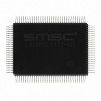
LAN91C111I-NS SMSC, LAN91C111I-NS Datasheet - Page 16

LAN91C111I-NS
Manufacturer Part Number
LAN91C111I-NS
Description
IC ETHERNET CTLR MAC PHY 128-QFP
Manufacturer
SMSC
Type
Single Chip MAC and PHYr
Datasheet
1.LAN91C111-NU.pdf
(128 pages)
Specifications of LAN91C111I-NS
Controller Type
Ethernet Controller, MAC/PHY
Interface
Serial EEPROM
Voltage - Supply
3.3V
Operating Temperature
-40°C ~ 85°C
Mounting Type
Surface Mount
Package / Case
128-QFP
Product
Ethernet Controllers
Number Of Transceivers
1
Standard Supported
IEEE 802.3 or IEEE 802.3u
Data Rate
10 Mbps or 100 Mbps
Supply Voltage (max)
5 V
Supply Voltage (min)
0 V
Supply Current (max)
140 mA
Maximum Operating Temperature
+ 85 C
Ethernet Connection Type
100BASE-T or 100BASE-T4 or 100BASE-TX or 10BASE-T
Minimum Operating Temperature
- 40 C
Mounting Style
SMD/SMT
Lead Free Status / RoHS Status
Lead free / RoHS Compliant
Current - Supply
-
Lead Free Status / Rohs Status
Lead free / RoHS Compliant
Other names
638-1014
Available stocks
Company
Part Number
Manufacturer
Quantity
Price
Company:
Part Number:
LAN91C111I-NS
Manufacturer:
RECOM
Quantity:
1 000
Company:
Part Number:
LAN91C111I-NS
Manufacturer:
SMSC
Quantity:
1 000
Company:
Part Number:
LAN91C111I-NS
Manufacturer:
Standard
Quantity:
6 916
Company:
Part Number:
LAN91C111I-NS
Manufacturer:
Microchip Technology
Quantity:
10 000
Revision 1.91 (06-01-09)
PIN NO.
TQFP
42
38
43
46
29
45
31
32
34
QFP
44
40
45
48
31
47
33
34
36
NAME
Local Bus Clock LCLK
Asynchronous
Ready
nSynchronous
Ready
nReady Return
Interrupt
nLocal Device
nRead Strobe
nWrite Strobe
nData Path
Chip Select
INTR0
nLDEV
nWR
SYMBOL
ARDY
nSRDY
nRDYRTN
nRD
nDATACS
DATASHEET
16
BUFFER
TYPE
I**
OD16
O16
I**
O24
O16
IS**
IS**
I with
pullup**
10/100 Non-PCI Ethernet Single Chip MAC + PHY
DESCRIPTION
Input. Used to interface synchronous
buses. Maximum frequency is 50 MHz.
Limited to 8.33 MHz for EISA DMA burst
mode. This pin should be tied high if it is
in asynchronous mode.
Open drain output. ARDY may be used
when interfacing asynchronous buses to
extend accesses. Its rising (access
completion) edge is controlled by the
XTAL1 clock and, therefore,
asynchronous to the host CPU or bus
clock. ARDY is negated during
Asynchronous cycle when one of the
following conditions occurs:
No_Wait Bit in the Configuration Register
is cleared.
Read FIFO contains less than 4 bytes
when read.
Write FIFO is full when write.
Output. This output is used when
interfacing synchronous buses and
nVLBUS=0 to extend accesses. This
signal remains normally inactive, and its
falling edge indicates completion. This
signal is synchronous to the bus clock
LCLK.
Input. This input is used to complete
synchronous read cycles. In EISA burst
mode it is sampled on falling LCLK
edges, and synchronous cycles are
delayed until it is sampled high.
Interrupt Output – Active High, it’s used to
interrupt the Host on a status event.
Note: The selection bits used to
determined by the value of INT SEL 1-0
bits in the Configuration Register are no
longer required and have been set to
reserved in this revision of the FEAST
family of devices.
Output. This active low output is asserted
when AEN is low and A4-A15 decode to
the LAN91C111 address programmed
into the high byte of the Base Address
Register. nLDEV is a combinatorial
decode of unlatched address and AEN
signals.
Input. Used in asynchronous bus
interfaces.
Input. Used in asynchronous bus
interfaces.
Input. When nDATACS is low, the Data
Path can be accessed regardless of the
values of AEN, A1-A15 and the content of
the BANK SELECT Register. nDATACS
provides an interface for bursting to and
from the LAN91C111 32 bits at a time.
SMSC LAN91C111 REV C
Datasheet


