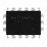
LAN91C111I-NS SMSC, LAN91C111I-NS Datasheet - Page 57

LAN91C111I-NS
Manufacturer Part Number
LAN91C111I-NS
Description
IC ETHERNET CTLR MAC PHY 128-QFP
Manufacturer
SMSC
Type
Single Chip MAC and PHYr
Datasheet
1.LAN91C111-NU.pdf
(128 pages)
Specifications of LAN91C111I-NS
Controller Type
Ethernet Controller, MAC/PHY
Interface
Serial EEPROM
Voltage - Supply
3.3V
Operating Temperature
-40°C ~ 85°C
Mounting Type
Surface Mount
Package / Case
128-QFP
Product
Ethernet Controllers
Number Of Transceivers
1
Standard Supported
IEEE 802.3 or IEEE 802.3u
Data Rate
10 Mbps or 100 Mbps
Supply Voltage (max)
5 V
Supply Voltage (min)
0 V
Supply Current (max)
140 mA
Maximum Operating Temperature
+ 85 C
Ethernet Connection Type
100BASE-T or 100BASE-T4 or 100BASE-TX or 10BASE-T
Minimum Operating Temperature
- 40 C
Mounting Style
SMD/SMT
Lead Free Status / RoHS Status
Lead free / RoHS Compliant
Current - Supply
-
Lead Free Status / Rohs Status
Lead free / RoHS Compliant
Other names
638-1014
Available stocks
Company
Part Number
Manufacturer
Quantity
Price
Company:
Part Number:
LAN91C111I-NS
Manufacturer:
RECOM
Quantity:
1 000
Company:
Part Number:
LAN91C111I-NS
Manufacturer:
SMSC
Quantity:
1 000
Company:
Part Number:
LAN91C111I-NS
Manufacturer:
Standard
Quantity:
6 916
Company:
Part Number:
LAN91C111I-NS
Manufacturer:
Microchip Technology
Quantity:
10 000
10/100 Non-PCI Ethernet Single Chip MAC + PHY
Datasheet
SMSC LAN91C111 REV C
8.15
LOW BYTE
BYTE
HIGH
Bank 1 - Control Register
RCV_BAD - When set, bad CRC packets are received. When clear bad CRC packets do not generate
interrupts and their memory is released.
AUTO RELEASE - When set, transmit pages are released by transmit completion if the transmission
was successful (when TX_SUC is set). In that case there is no status word associated with its packet
number, and successful packet numbers are not even written into the TX COMPLETION FIFO. A
sequence of transmit packets will generate an interrupt only when the sequence is completely
transmitted (TX EMPTY INT will be set), or when a packet in the sequence experiences a fatal error
(TX INT will be set). Upon a fatal error TXENA is cleared and the transmission sequence stops. The
packet number that failed, is present in the FIFO PORTS register, and its pages are not released,
allowing the CPU to restart the sequence after corrective action is taken.
LE ENABLE - Link Error Enable. When set it enables the LINK_OK bit transition as one of the
interrupts merged into the EPH INT bit. Clearing the LE ENABLE bit after an EPH INT interrupt, caused
by a LINK_OK transition, will acknowledge the interrupt. LE ENABLE defaults low (disabled).
CR ENABLE - Counter Roll over Enable. When set, it enables the CTR_ROL bit as one of the
interrupts merged into the EPH INT bit. Reading the COUNTER register after an EPH INT interrupt
caused by a counter rollover, will acknowledge the interrupt. CR ENABLE defaults low (disabled).
TE ENABLE - Transmit Error Enable. When set it enables Transmit Error as one of the interrupts
merged into the EPH INT bit. An EPH INT interrupt caused by a transmitter error is acknowledged by
setting TXENA bit in the TCR register to 1 or by clearing the TE ENABLE bit. TE ENABLE defaults
low (disabled). Transmit Error is any condition that clears TXENA with TX_SUC staying low as
described in the EPHSR register.
EEPROM SELECT - This bit allows the CPU to specify which registers the EEPROM RELOAD or
STORE refers to. When high, the General Purpose Register is the only register read or written. When
low, RELOAD reads Configuration, Base and Individual Address, and STORE writes the Configuration
and Base registers.
RELOAD - When set it will read the EEPROM and update relevant registers with its contents. Clears
upon completing the operation.
STORE - When set, stores the contents of all relevant registers in the serial EEPROM. Clears upon
completing the operation.
Note: When an EEPROM access is in progress the STORE and RELOAD bits will be read back as
Reserved
ENABLE
LE
0
0
OFFSET
high. The remaining 14 bits of this register will be invalid. During this time attempted read/write
operations, other than polling the EEPROM status, will NOT have any effect on the internal
registers. The CPU can resume accesses to the LAN91C111 after both bits are low. A worst
case RELOAD operation initiated by RESET or by software takes less than 750 μs.
C
ENABLE
RCV_
BAD
CR
0
0
CONTROL REGISTER
Reserved
ENABLE
NAME
TE
0
0
DATASHEET
Reserved
Reserved
57
1
1
READ/WRITE
RELEASE
Reserved
TYPE
AUTO
0
0
EEPROM
Reserved
SELECT
0
0
SYMBOL
CTR
Reserved
RELOAD
Revision 1.91 (06-01-09)
1
0
Reserved
STORE
0
0


