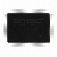
LAN91C111I-NS SMSC, LAN91C111I-NS Datasheet - Page 87

LAN91C111I-NS
Manufacturer Part Number
LAN91C111I-NS
Description
IC ETHERNET CTLR MAC PHY 128-QFP
Manufacturer
SMSC
Type
Single Chip MAC and PHYr
Datasheet
1.LAN91C111-NU.pdf
(128 pages)
Specifications of LAN91C111I-NS
Controller Type
Ethernet Controller, MAC/PHY
Interface
Serial EEPROM
Voltage - Supply
3.3V
Operating Temperature
-40°C ~ 85°C
Mounting Type
Surface Mount
Package / Case
128-QFP
Product
Ethernet Controllers
Number Of Transceivers
1
Standard Supported
IEEE 802.3 or IEEE 802.3u
Data Rate
10 Mbps or 100 Mbps
Supply Voltage (max)
5 V
Supply Voltage (min)
0 V
Supply Current (max)
140 mA
Maximum Operating Temperature
+ 85 C
Ethernet Connection Type
100BASE-T or 100BASE-T4 or 100BASE-TX or 10BASE-T
Minimum Operating Temperature
- 40 C
Mounting Style
SMD/SMT
Lead Free Status / RoHS Status
Lead free / RoHS Compliant
Current - Supply
-
Lead Free Status / Rohs Status
Lead free / RoHS Compliant
Other names
638-1014
Available stocks
Company
Part Number
Manufacturer
Quantity
Price
Company:
Part Number:
LAN91C111I-NS
Manufacturer:
RECOM
Quantity:
1 000
Company:
Part Number:
LAN91C111I-NS
Manufacturer:
SMSC
Quantity:
1 000
Company:
Part Number:
LAN91C111I-NS
Manufacturer:
Standard
Quantity:
6 916
Company:
Part Number:
LAN91C111I-NS
Manufacturer:
Microchip Technology
Quantity:
10 000
10/100 Non-PCI Ethernet Single Chip MAC + PHY
Datasheet
SMSC LAN91C111 REV C
10.4
7
8
1
2
3
4
5
S/W DRIVER
SERVICE INTERRUPT – Read Interrupt Status
Register, exit the interrupt service routine.
Option 1) Release the packet.
Option 2) Check the transmit status in the EPH
STATUS Register, write the packet number of the
current packet to the Packet Number Register, re-
enable TXENA, then go to step 4 to start the TX
sequence again.
S/W DRIVER
ENABLE RECEPTION - By setting the RXEN bit.
SERVICE INTERRUPT - Read the Interrupt Status
Register and determine if RCV INT is set. The next
receive packet is at receive area. (Its packet number
can be read from the FIFO Ports Register). The
software driver can process the packet by accessing
the RX area, and can move it out to system memory
if desired. When processing is complete the CPU
issues the REMOVE AND RELEASE FROM TOP OF
RX command to have the MMU free up the used
memory and packet number.
Typical Flow of Event For Receive
DATASHEET
87
MAC SIDE
The MAC generates a TXEMPTY interrupt upon a
completion of a sequence of enqueued packets.
If a TX failure occurs on any packets, TX INT is
generated and TXENA is cleared, transmission
sequence stops. The packet number of the failure
packet is presented at the TX FIFO PORTS Register.
MAC SIDE
A packet is received with matching address. Memory
is requested from MMU. A packet number is
assigned to it. Additional memory is requested if
more pages are needed.
The internal DMA logic generates sequential
addresses and writes the receive words into memory.
The MMU does the sequential to physical address
translation. If overrun, packet is dropped and
memory is released.
When the end of packet is detected, the status word
is placed at the beginning of the receive packet in
memory. Byte count is placed at the second word. If
the CRC checks correctly the packet number is
written into the RX FIFO. The RX FIFO, being not
empty, causes RCV INT (interrupt) to be set. The
RCV_BAD bit of the Bank 1 Control Register controls
whether or not to generate interrupts when bad CRC
packets are received.
Revision 1.91 (06-01-09)


