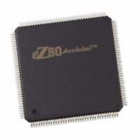
EZ80F91AZ050EG Zilog, EZ80F91AZ050EG Datasheet - Page 191

EZ80F91AZ050EG
Manufacturer Part Number
EZ80F91AZ050EG
Description
IC ACCLAIM MCU 256KB 144LQFP
Manufacturer
Zilog
Series
eZ80® Acclaim!®r
Specifications of EZ80F91AZ050EG
Core Processor
Z8
Core Size
8-Bit
Speed
50MHz
Connectivity
Ethernet, I²C, IrDA, SPI, UART/USART
Peripherals
Brown-out Detect/Reset, POR, PWM, WDT
Number Of I /o
32
Program Memory Size
256KB (256K x 8)
Program Memory Type
FLASH
Ram Size
16K x 8
Voltage - Supply (vcc/vdd)
3 V ~ 3.6 V
Oscillator Type
Internal
Operating Temperature
-40°C ~ 105°C
Package / Case
144-LQFP
Processor Series
EZ80F91x
Core
eZ80
Data Bus Width
8 bit
Data Ram Size
16 KB
Interface Type
I2C, IrDA, SPI, UART
Maximum Clock Frequency
50 MHz
Number Of Programmable I/os
32
Number Of Timers
4
Operating Supply Voltage
3 V to 3.6 V
Maximum Operating Temperature
+ 105 C
Mounting Style
SMD/SMT
Development Tools By Supplier
eZ80F910300ZCOG
Minimum Operating Temperature
- 40 C
For Use With
269-4712 - KIT DEV ENCORE 32 SERIES269-4671 - BOARD ZDOTS SBC Z80ACCLAIM PLUS269-4561 - KIT DEV FOR EZ80F91 W/C-COMPILER269-4560 - KIT DEV FOR EZ80F91 W/C-COMPILER
Lead Free Status / RoHS Status
Lead free / RoHS Compliant
Eeprom Size
-
Data Converters
-
Lead Free Status / Rohs Status
Details
Other names
269-3867
EZ80F91AZ050EG
EZ80F91AZ050EG
Available stocks
Company
Part Number
Manufacturer
Quantity
Price
- Current page: 191 of 384
- Download datasheet (3Mb)
Table 94. UART Baud Rate Generator Register—Low Bytes
UART1_BRG_L = 00D0h)
PS019215-0910
Bit
Reset
CPU Access
Note: R = Read only; R/W = Read/Write.
Bit
Position
[7:0]
UART_BRG_L
Note:
BRG Control Registers
UART Baud Rate Generator Register—Low and High Bytes
The registers hold the Low and High bytes of the 16-bit divisor count loaded by the CPU
for UART baud rate generation. The 16-bit clock divisor value is returned by
{UARTx_BRG_H, UARTx_BRG_L}, where x is either 0 or 1 to identify the two available
UART devices. Upon RESET, the 16-bit BRG divisor value resets to
16-bit divisor value must be between
0001h
the minimum BRG clock divisor ratio is 2.
A Write to either the Low- or High-byte registers for the BRG Divisor Latch causes both
bytes to be loaded into the BRG counter. The count is then restarted.
Bit 7 of the associated UART Line Control register (UARTx_LCTL) must be set to 1 to
access this register. See
UART Line Control Register
The UARTx_BRG_L registers share the same address space with the UARTx_RBR and
UARTx_THR registers. The UARTx_BRG_H registers share the same address space with
the UARTx_IER registers. Bit 7 of the associated UART Line Control register
(UARTx_LCTL) must be set to 1 to enable access to the BRG registers.
Value
00h–FFh
are invalid and proper operation is not guaranteed at these two values. As a result,
R/W
7
0
Description
These bits represent the Low byte of the 16-bit BRG divider value. The
complete BRG divisor value is returned by {UART_BRG_H,
UART_BRG_L}.
R/W
Table 94
6
0
on page 188.
R/W
and
5
0
0002h
Table 95
R/W
4
0
and
on page 183. For more information, see
Universal Asynchronous Receiver/Transmitter
FFFFh
R/W
3
0
(UART0_BRG_L = 00C0h,
, because the values
R/W
2
0
Product Specification
0002h
R/W
1
1
eZ80F91 MCU
. The initial
0000h
R/W
0
0
and
182
Related parts for EZ80F91AZ050EG
Image
Part Number
Description
Manufacturer
Datasheet
Request
R

Part Number:
Description:
Communication Controllers, ZILOG INTELLIGENT PERIPHERAL CONTROLLER (ZIP)
Manufacturer:
Zilog, Inc.
Datasheet:

Part Number:
Description:
KIT DEV FOR Z8 ENCORE 16K TO 64K
Manufacturer:
Zilog
Datasheet:

Part Number:
Description:
KIT DEV Z8 ENCORE XP 28-PIN
Manufacturer:
Zilog
Datasheet:

Part Number:
Description:
DEV KIT FOR Z8 ENCORE 8K/4K
Manufacturer:
Zilog
Datasheet:

Part Number:
Description:
KIT DEV Z8 ENCORE XP 28-PIN
Manufacturer:
Zilog
Datasheet:

Part Number:
Description:
DEV KIT FOR Z8 ENCORE 4K TO 8K
Manufacturer:
Zilog
Datasheet:

Part Number:
Description:
CMOS Z8 microcontroller. ROM 16 Kbytes, RAM 256 bytes, speed 16 MHz, 32 lines I/O, 3.0V to 5.5V
Manufacturer:
Zilog, Inc.
Datasheet:

Part Number:
Description:
Low-cost microcontroller. 512 bytes ROM, 61 bytes RAM, 8 MHz
Manufacturer:
Zilog, Inc.
Datasheet:

Part Number:
Description:
Z8 4K OTP Microcontroller
Manufacturer:
Zilog, Inc.
Datasheet:

Part Number:
Description:
CMOS SUPER8 ROMLESS MCU
Manufacturer:
Zilog, Inc.
Datasheet:

Part Number:
Description:
SL1866 CMOSZ8 OTP Microcontroller
Manufacturer:
Zilog, Inc.
Datasheet:

Part Number:
Description:
SL1866 CMOSZ8 OTP Microcontroller
Manufacturer:
Zilog, Inc.
Datasheet:

Part Number:
Description:
OTP (KB) = 1, RAM = 125, Speed = 12, I/O = 14, 8-bit Timers = 2, Comm Interfaces Other Features = Por, LV Protect, Voltage = 4.5-5.5V
Manufacturer:
Zilog, Inc.
Datasheet:

Part Number:
Description:
Manufacturer:
Zilog, Inc.
Datasheet:


