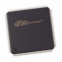
EZ80F91AZ050EG Zilog, EZ80F91AZ050EG Datasheet - Page 298

EZ80F91AZ050EG
Manufacturer Part Number
EZ80F91AZ050EG
Description
IC ACCLAIM MCU 256KB 144LQFP
Manufacturer
Zilog
Series
eZ80® Acclaim!®r
Specifications of EZ80F91AZ050EG
Core Processor
Z8
Core Size
8-Bit
Speed
50MHz
Connectivity
Ethernet, I²C, IrDA, SPI, UART/USART
Peripherals
Brown-out Detect/Reset, POR, PWM, WDT
Number Of I /o
32
Program Memory Size
256KB (256K x 8)
Program Memory Type
FLASH
Ram Size
16K x 8
Voltage - Supply (vcc/vdd)
3 V ~ 3.6 V
Oscillator Type
Internal
Operating Temperature
-40°C ~ 105°C
Package / Case
144-LQFP
Processor Series
EZ80F91x
Core
eZ80
Data Bus Width
8 bit
Data Ram Size
16 KB
Interface Type
I2C, IrDA, SPI, UART
Maximum Clock Frequency
50 MHz
Number Of Programmable I/os
32
Number Of Timers
4
Operating Supply Voltage
3 V to 3.6 V
Maximum Operating Temperature
+ 105 C
Mounting Style
SMD/SMT
Development Tools By Supplier
eZ80F910300ZCOG
Minimum Operating Temperature
- 40 C
For Use With
269-4712 - KIT DEV ENCORE 32 SERIES269-4671 - BOARD ZDOTS SBC Z80ACCLAIM PLUS269-4561 - KIT DEV FOR EZ80F91 W/C-COMPILER269-4560 - KIT DEV FOR EZ80F91 W/C-COMPILER
Lead Free Status / RoHS Status
Lead free / RoHS Compliant
Eeprom Size
-
Data Converters
-
Lead Free Status / Rohs Status
Details
Other names
269-3867
EZ80F91AZ050EG
EZ80F91AZ050EG
Available stocks
Company
Part Number
Manufacturer
Quantity
Price
- Current page: 298 of 384
- Download datasheet (3Mb)
eZ80F91 MCU
Product Specification
289
EmacRHBP, points to the end of the Rx buffer + 1. The Tx and Receive buffers are
divided into packet buffers of either 256, 128, 64, or 32 bytes. These buffer sizes are
selected by EmacBufSize register bits 7 and 6.
The EmacBlksLeft register contains the number of Receive packet buffers remaining in
the Rx buffer. This buffer is used for software flow control. If the Block_Level is nonzero
(bits 5:0 of the EmacBufSize register), hardware flow control is enabled. If in FULL-
DUPLEX mode, the EMAC transmits a pause control frame when the EmacBlksLeft reg-
ister is less than the Block_Level. In HALF-DUPLEX mode, the EMAC continually trans-
mits a nibble pattern of hexadecimal 5’s to jam the channel.
Four pointers are defined for reading and writing the Tx and Rx buffers. The Transmit
Write Pointer, TWP, is a software pointer that points to the next available packet buffer.
The TWP is reset to the value stored in EmacTLBP. The Transmit Read Pointer, TRP, is a
hardware pointer in the Transmit Direct Memory Access Register, TxDMA, that contains
the address of the next packet to be transmitted. It is automatically reset to the EmacTLBP.
The Receive Write Pointer, RWP, is a hardware pointer in the Receive Direct Memory
Access Register, RxDMA, which contains the storage address of the incoming packet. The
RWP pointer is automatically initialized to the Boundary Pointer registers. The Receive
Read Pointer, RRP, is a software pointer to where the next packet must be read from. The
RRP pointer must be initialized to the Boundary Pointer registers. For the hardware flow
control to function properly, the software must update the hardware RRP (EmacRrp)
pointer whenever the software version is updated. The RxDMA uses RWP and the RRP to
determine how many packet buffers remain in the Rx buffer.
Arbiter
The arbiter controls access to EMAC memory. It prioritizes the requests for memory
access between the CPU, the TxDMA, and the RxDMA. The TxDMA offers two levels of
priority: a high priority when the TxFIFO is less than half full and a Low priority when the
TxFIFO is more than half full. Similarly, the RxDMA offers two levels of priority: a high
priority when the RxFIFO is more than half full and a Low priority when the RxFIFO is
less than half full.
The arbiter determines resolution between the CPU, the RxDMA, and the TxDMA
requests to access EMAC memory. Post writing for CPU Writes results in Zero-Wait-state
write access timing when the CPU assumes the highest priority. CPU Reads require a min-
imum of 1 Wait state and takes more when the CPU does not hold the highest priority. The
CPU Read Wait state is not a user-controllable operation, because it is controlled by the
arbiter. The RxDMA and TxDMA requests are not allowed to occur back-to-back. There-
fore, the maximum throughput rate for the two Direct Memory Access (DMA) ports is 25
Mbps each (one byte every 2 clocks) when the system clock is running at 50 MHz. The
rate is reduced to 20 MBps for a 40 MHz system clock. The arbiter uses the internal WAIT
signal to add Wait states to CPU access when required. See
Table 174
on page 290.
PS019215-0910
Ethernet Media Access Controller
Related parts for EZ80F91AZ050EG
Image
Part Number
Description
Manufacturer
Datasheet
Request
R

Part Number:
Description:
Communication Controllers, ZILOG INTELLIGENT PERIPHERAL CONTROLLER (ZIP)
Manufacturer:
Zilog, Inc.
Datasheet:

Part Number:
Description:
KIT DEV FOR Z8 ENCORE 16K TO 64K
Manufacturer:
Zilog
Datasheet:

Part Number:
Description:
KIT DEV Z8 ENCORE XP 28-PIN
Manufacturer:
Zilog
Datasheet:

Part Number:
Description:
DEV KIT FOR Z8 ENCORE 8K/4K
Manufacturer:
Zilog
Datasheet:

Part Number:
Description:
KIT DEV Z8 ENCORE XP 28-PIN
Manufacturer:
Zilog
Datasheet:

Part Number:
Description:
DEV KIT FOR Z8 ENCORE 4K TO 8K
Manufacturer:
Zilog
Datasheet:

Part Number:
Description:
CMOS Z8 microcontroller. ROM 16 Kbytes, RAM 256 bytes, speed 16 MHz, 32 lines I/O, 3.0V to 5.5V
Manufacturer:
Zilog, Inc.
Datasheet:

Part Number:
Description:
Low-cost microcontroller. 512 bytes ROM, 61 bytes RAM, 8 MHz
Manufacturer:
Zilog, Inc.
Datasheet:

Part Number:
Description:
Z8 4K OTP Microcontroller
Manufacturer:
Zilog, Inc.
Datasheet:

Part Number:
Description:
CMOS SUPER8 ROMLESS MCU
Manufacturer:
Zilog, Inc.
Datasheet:

Part Number:
Description:
SL1866 CMOSZ8 OTP Microcontroller
Manufacturer:
Zilog, Inc.
Datasheet:

Part Number:
Description:
SL1866 CMOSZ8 OTP Microcontroller
Manufacturer:
Zilog, Inc.
Datasheet:

Part Number:
Description:
OTP (KB) = 1, RAM = 125, Speed = 12, I/O = 14, 8-bit Timers = 2, Comm Interfaces Other Features = Por, LV Protect, Voltage = 4.5-5.5V
Manufacturer:
Zilog, Inc.
Datasheet:

Part Number:
Description:
Manufacturer:
Zilog, Inc.
Datasheet:


