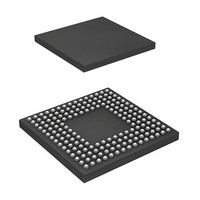
DF2552BR26DV Renesas Electronics America, DF2552BR26DV Datasheet - Page 12

DF2552BR26DV
Manufacturer Part Number
DF2552BR26DV
Description
IC H8S/2552 MCU FLASH 176-LFBGA
Manufacturer
Renesas Electronics America
Series
H8® H8S/2500r
Specifications of DF2552BR26DV
Core Processor
H8S/2000
Core Size
16-Bit
Speed
26MHz
Connectivity
I²C, SCI
Peripherals
POR, PWM, WDT
Number Of I /o
104
Program Memory Size
512KB (512K x 8)
Program Memory Type
FLASH
Ram Size
32K x 8
Voltage - Supply (vcc/vdd)
3 V ~ 5.5 V
Data Converters
A/D 16x10b; D/A 2x8b
Oscillator Type
Internal
Operating Temperature
-40°C ~ 85°C
Package / Case
176-LFBGA
Lead Free Status / RoHS Status
Lead free / RoHS Compliant
Eeprom Size
-
Available stocks
Company
Part Number
Manufacturer
Quantity
Price
Company:
Part Number:
DF2552BR26DV
Manufacturer:
Renesas Electronics America
Quantity:
10 000
- Current page: 12 of 980
- Download datasheet (6Mb)
2.8
2.9
Section 3 MCU Operating Modes ......................................................................... 67
3.1
3.2
3.3
3.4
Section 4 Exception Handling ............................................................................... 75
4.1
4.2
4.3
4.4
4.5
4.6
4.7
4.8
Section 5 Interrupt Controller................................................................................ 85
5.1
5.2
5.3
Rev. 6.00 Sep. 24, 2009 Page x of xlvi
REJ09B0099-0600
2.7.7
2.7.8
2.7.9
Processing States.................................................................................................................. 59
Usage Notes ......................................................................................................................... 61
2.9.1
2.9.2
2.9.3
2.9.4
Operating Mode Selection ................................................................................................... 67
Register Descriptions........................................................................................................... 68
3.2.1
3.2.2
Operating Mode ................................................................................................................... 70
3.3.1
3.3.2
3.3.3
Address Map in Each Operating Mode................................................................................ 72
Exception Handling Types and Priority............................................................................... 75
Exception Sources and Exception Vector Table .................................................................. 75
Reset .................................................................................................................................... 77
4.3.1
4.3.2
4.3.3
4.3.4
Trace Exception Handling ................................................................................................... 79
Interrupt Exception Handling .............................................................................................. 80
Trap Instruction Exception Handling................................................................................... 80
Stack State after Exception Handling .................................................................................. 82
Usage Note........................................................................................................................... 82
Features................................................................................................................................ 85
Input/Output Pins................................................................................................................. 87
Register Descriptions........................................................................................................... 88
5.3.1
Program-Counter Relative⎯@(d:8, PC) or @(d:16, PC) ...................................... 55
Memory Indirect⎯@@aa:8 ................................................................................... 55
Effective Address Calculation ................................................................................ 56
TAS Instruction ...................................................................................................... 61
STM/LDM Instruction............................................................................................ 61
Bit Manipulation Instructions ................................................................................. 61
Access Method for Registers with Write-Only Bits ............................................... 63
Mode Control Register (MDCR) ............................................................................ 68
System Control Register (SYSCR)......................................................................... 68
Mode 6.................................................................................................................... 70
Mode 7.................................................................................................................... 70
Pin Functions .......................................................................................................... 70
Types of Reset ........................................................................................................ 77
Reset Exception Handling ...................................................................................... 78
Interrupts after Reset............................................................................................... 79
State of On-Chip Peripheral Modules after Reset Release ..................................... 79
Interrupt Priority Registers A to M, and O (IPRA to IPRM, IPRO)....................... 89
Related parts for DF2552BR26DV
Image
Part Number
Description
Manufacturer
Datasheet
Request
R

Part Number:
Description:
KIT STARTER FOR M16C/29
Manufacturer:
Renesas Electronics America
Datasheet:

Part Number:
Description:
KIT STARTER FOR R8C/2D
Manufacturer:
Renesas Electronics America
Datasheet:

Part Number:
Description:
R0K33062P STARTER KIT
Manufacturer:
Renesas Electronics America
Datasheet:

Part Number:
Description:
KIT STARTER FOR R8C/23 E8A
Manufacturer:
Renesas Electronics America
Datasheet:

Part Number:
Description:
KIT STARTER FOR R8C/25
Manufacturer:
Renesas Electronics America
Datasheet:

Part Number:
Description:
KIT STARTER H8S2456 SHARPE DSPLY
Manufacturer:
Renesas Electronics America
Datasheet:

Part Number:
Description:
KIT STARTER FOR R8C38C
Manufacturer:
Renesas Electronics America
Datasheet:

Part Number:
Description:
KIT STARTER FOR R8C35C
Manufacturer:
Renesas Electronics America
Datasheet:

Part Number:
Description:
KIT STARTER FOR R8CL3AC+LCD APPS
Manufacturer:
Renesas Electronics America
Datasheet:

Part Number:
Description:
KIT STARTER FOR RX610
Manufacturer:
Renesas Electronics America
Datasheet:

Part Number:
Description:
KIT STARTER FOR R32C/118
Manufacturer:
Renesas Electronics America
Datasheet:

Part Number:
Description:
KIT DEV RSK-R8C/26-29
Manufacturer:
Renesas Electronics America
Datasheet:

Part Number:
Description:
KIT STARTER FOR SH7124
Manufacturer:
Renesas Electronics America
Datasheet:

Part Number:
Description:
KIT STARTER FOR H8SX/1622
Manufacturer:
Renesas Electronics America
Datasheet:

Part Number:
Description:
KIT DEV FOR SH7203
Manufacturer:
Renesas Electronics America
Datasheet:


