DF2552BR26DV Renesas Electronics America, DF2552BR26DV Datasheet - Page 47
DF2552BR26DV
Manufacturer Part Number
DF2552BR26DV
Description
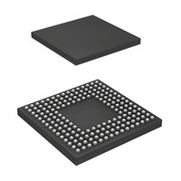
IC H8S/2552 MCU FLASH 176-LFBGA
Manufacturer
Renesas Electronics America
Series
H8® H8S/2500r
Specifications of DF2552BR26DV
Core Processor
H8S/2000
Core Size
16-Bit
Speed
26MHz
Connectivity
I²C, SCI
Peripherals
POR, PWM, WDT
Number Of I /o
104
Program Memory Size
512KB (512K x 8)
Program Memory Type
FLASH
Ram Size
32K x 8
Voltage - Supply (vcc/vdd)
3 V ~ 5.5 V
Data Converters
A/D 16x10b; D/A 2x8b
Oscillator Type
Internal
Operating Temperature
-40°C ~ 85°C
Package / Case
176-LFBGA
Lead Free Status / RoHS Status
Lead free / RoHS Compliant
Eeprom Size
-
Available stocks
Company
Part Number
Manufacturer
Quantity
Price
Company:

Part Number:
DF2552BR26DV
Manufacturer:
Renesas Electronics America
Quantity:
10 000


Table 17.4
Table 17.5
Table 17.6
Table 17.7
Section 18 Controller Area Network (HCAN) [H8S/2556 Group]
Table 18.1
Table 18.2
Table 18.3
Table 18.4
Table 18.5
Section 20 Flash Memory
Table 20.1
Table 20.2
Table 20.3
Table 20.4
Table 20.5
Table 20.6
Table 20.7
Table 20.8
Table 20.9 (1)
Table 20.9 (2)
Table 20.9 (3)
Table 20.9 (4)
Table 20.10 Hardware Protection................................................................................................ 726
Table 20.11 Software Protection ................................................................................................. 727
Table 20.12 Setting Procedure of each Operation Mode of Programmer Mode ......................... 736
Table 20.13 Each Command in Programmer Mode .................................................................... 737
Table 20.14 Return Codes in Status-Read Mode ........................................................................ 739
Table 20.15 True Value Table of Status Polling Output ............................................................. 739
Table 20.16 Inquiry and Selection Commands ........................................................................... 745
Table 20.17 Programming/Erasing Command ............................................................................ 756
Table 20.18 Status Code.............................................................................................................. 766
Table 20.19 Error Code............................................................................................................... 766
Table 20.20 AC Characteristics in Memory Read Mode ............................................................ 767
Table 20.21 AC Characteristics in Transition from Memory-Read Mode to Other Mode.......... 768
Table 20.22 AC Characteristics in Memory-Read Mode ............................................................ 769
Table 20.23 AC Characteristics in Auto-Program Mode ............................................................ 770
Table 20.24 AC Characteristic in Auto-Erase Mode................................................................... 771
Control Bit Contents................................................................................................ 551
Control Field for Locked Slave Unit ....................................................................... 552
Pin Configuration .................................................................................................... 556
List of System Clock Division Ratio....................................................................... 559
Pin Configuration .................................................................................................... 611
Limits for Settable Value ........................................................................................ 640
Setting Range for TSEG1 and TSEG2 in BCR ....................................................... 642
HCAN Interrupt Sources......................................................................................... 654
Interval Limitation between TXPR and TXPR or between TXPR and TXCR ....... 660
MD Pin Setting and Operating Mode...................................................................... 669
Comparison of Programming Modes ...................................................................... 670
Pin Configuration .................................................................................................... 675
Register/Parameter and Target Mode...................................................................... 677
Parameters and Target Modes ................................................................................. 685
Division of User MAT Area.................................................................................... 697
System Clock Frequency for Automatic-Bit-Rate Adjustment by This LSI ........... 700
Executable MAT ..................................................................................................... 719
Useable Area for Programming in User Program Mode................................... 719
Useable Area for Erasure in User Program Mode............................................. 721
Useable Area for Programming in User Boot Mode......................................... 722
Useable Area for Erasure in User Boot Mode .................................................. 724
Rev. 6.00 Sep. 24, 2009 Page xlv of xlvi
REJ09B0099-0600
Related parts for DF2552BR26DV
Image
Part Number
Description
Manufacturer
Datasheet
Request
R

Part Number:
Description:
KIT STARTER FOR M16C/29
Manufacturer:
Renesas Electronics America
Datasheet:

Part Number:
Description:
KIT STARTER FOR R8C/2D
Manufacturer:
Renesas Electronics America
Datasheet:

Part Number:
Description:
R0K33062P STARTER KIT
Manufacturer:
Renesas Electronics America
Datasheet:

Part Number:
Description:
KIT STARTER FOR R8C/23 E8A
Manufacturer:
Renesas Electronics America
Datasheet:

Part Number:
Description:
KIT STARTER FOR R8C/25
Manufacturer:
Renesas Electronics America
Datasheet:

Part Number:
Description:
KIT STARTER H8S2456 SHARPE DSPLY
Manufacturer:
Renesas Electronics America
Datasheet:

Part Number:
Description:
KIT STARTER FOR R8C38C
Manufacturer:
Renesas Electronics America
Datasheet:

Part Number:
Description:
KIT STARTER FOR R8C35C
Manufacturer:
Renesas Electronics America
Datasheet:

Part Number:
Description:
KIT STARTER FOR R8CL3AC+LCD APPS
Manufacturer:
Renesas Electronics America
Datasheet:
Part Number:
Description:
KIT STARTER FOR RX610
Manufacturer:
Renesas Electronics America
Datasheet:

Part Number:
Description:
KIT STARTER FOR R32C/118
Manufacturer:
Renesas Electronics America
Datasheet:

Part Number:
Description:
KIT DEV RSK-R8C/26-29
Manufacturer:
Renesas Electronics America
Datasheet:

Part Number:
Description:
KIT STARTER FOR SH7124
Manufacturer:
Renesas Electronics America
Datasheet:

Part Number:
Description:
KIT STARTER FOR H8SX/1622
Manufacturer:
Renesas Electronics America
Datasheet:

Part Number:
Description:
KIT DEV FOR SH7203
Manufacturer:
Renesas Electronics America
Datasheet: