DF2552BR26DV Renesas Electronics America, DF2552BR26DV Datasheet - Page 572
DF2552BR26DV
Manufacturer Part Number
DF2552BR26DV
Description
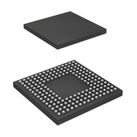
IC H8S/2552 MCU FLASH 176-LFBGA
Manufacturer
Renesas Electronics America
Series
H8® H8S/2500r
Specifications of DF2552BR26DV
Core Processor
H8S/2000
Core Size
16-Bit
Speed
26MHz
Connectivity
I²C, SCI
Peripherals
POR, PWM, WDT
Number Of I /o
104
Program Memory Size
512KB (512K x 8)
Program Memory Type
FLASH
Ram Size
32K x 8
Voltage - Supply (vcc/vdd)
3 V ~ 5.5 V
Data Converters
A/D 16x10b; D/A 2x8b
Oscillator Type
Internal
Operating Temperature
-40°C ~ 85°C
Package / Case
176-LFBGA
Lead Free Status / RoHS Status
Lead free / RoHS Compliant
Eeprom Size
-
Available stocks
Company
Part Number
Manufacturer
Quantity
Price
Company:

Part Number:
DF2552BR26DV
Manufacturer:
Renesas Electronics America
Quantity:
10 000


Section 15 A/D Converter
15.5.3
The A/D converter has a built-in sample-and-hold circuit. The A/D converter samples the analog
input when the A/D conversion start delay time (t
starts conversion. Figure 15.5 shows the A/D conversion timing. Table 15.3 shows the A/D
conversion time.
As indicated in figure 15.5, the A/D conversion time (t
(t
conversion time therefore varies within the ranges indicated in table 15.3. Specify the conversion
time by setting bits CKS0 and CKS1 in ADCR with ADST cleared to 0. Note that the specified
conversion time should be longer than the value described in section 24.5 A/D Conversion
Characteristics.
In scan mode, the values given in table 15.3 apply to the first conversion time. The values given in
table 15.4 apply to the second and subsequent conversions.
Rev. 6.00 Sep. 24, 2009 Page 524 of 928
REJ09B0099-0600
SPL
channel 3 (AN3)
channel 2 (AN2)
channel 0 (AN0)
channel 1 (AN1)
). The length of t
Notes: 1. Vertical arrows ( ) indicate instructions executed by software.
State of
State of
State of
State of
Figure 15.4 A/D Conversion Timing (Scan Mode, Channels AN0 to AN2 Selected)
ADDRA
ADDRB
ADDRC
ADDRD
ADST
ADF
Input Sampling and A/D Conversion Time
2. Data currently being converted is ignored.
Idle
D
varies depending on the timing of the write access to ADCSR. The total
Idle
A/D conversion 1
Set*
Idle
1
A/D conversion 2
Transfer
Continuous A/D conversion execution
A/D conversion result 1
Idle
D
A/D conversion 3
) has passed after the ADST bit is set to 1, then
Idle
CONV
Idle
) includes t
A/D conversion 4
A/D conversion time
A/D conversion result 2
D
A/D conversion result 3
and the input sampling time
A/D conversion 5
A/D conversion result 4
*
2
Clear*
Idle
Idle
Idle
1
Clear*
1
Related parts for DF2552BR26DV
Image
Part Number
Description
Manufacturer
Datasheet
Request
R

Part Number:
Description:
KIT STARTER FOR M16C/29
Manufacturer:
Renesas Electronics America
Datasheet:

Part Number:
Description:
KIT STARTER FOR R8C/2D
Manufacturer:
Renesas Electronics America
Datasheet:

Part Number:
Description:
R0K33062P STARTER KIT
Manufacturer:
Renesas Electronics America
Datasheet:

Part Number:
Description:
KIT STARTER FOR R8C/23 E8A
Manufacturer:
Renesas Electronics America
Datasheet:

Part Number:
Description:
KIT STARTER FOR R8C/25
Manufacturer:
Renesas Electronics America
Datasheet:

Part Number:
Description:
KIT STARTER H8S2456 SHARPE DSPLY
Manufacturer:
Renesas Electronics America
Datasheet:

Part Number:
Description:
KIT STARTER FOR R8C38C
Manufacturer:
Renesas Electronics America
Datasheet:

Part Number:
Description:
KIT STARTER FOR R8C35C
Manufacturer:
Renesas Electronics America
Datasheet:

Part Number:
Description:
KIT STARTER FOR R8CL3AC+LCD APPS
Manufacturer:
Renesas Electronics America
Datasheet:
Part Number:
Description:
KIT STARTER FOR RX610
Manufacturer:
Renesas Electronics America
Datasheet:

Part Number:
Description:
KIT STARTER FOR R32C/118
Manufacturer:
Renesas Electronics America
Datasheet:

Part Number:
Description:
KIT DEV RSK-R8C/26-29
Manufacturer:
Renesas Electronics America
Datasheet:

Part Number:
Description:
KIT STARTER FOR SH7124
Manufacturer:
Renesas Electronics America
Datasheet:

Part Number:
Description:
KIT STARTER FOR H8SX/1622
Manufacturer:
Renesas Electronics America
Datasheet:

Part Number:
Description:
KIT DEV FOR SH7203
Manufacturer:
Renesas Electronics America
Datasheet: