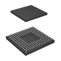
DF2552BR26DV Renesas Electronics America, DF2552BR26DV Datasheet - Page 602

DF2552BR26DV
Manufacturer Part Number
DF2552BR26DV
Description
IC H8S/2552 MCU FLASH 176-LFBGA
Manufacturer
Renesas Electronics America
Series
H8® H8S/2500r
Specifications of DF2552BR26DV
Core Processor
H8S/2000
Core Size
16-Bit
Speed
26MHz
Connectivity
I²C, SCI
Peripherals
POR, PWM, WDT
Number Of I /o
104
Program Memory Size
512KB (512K x 8)
Program Memory Type
FLASH
Ram Size
32K x 8
Voltage - Supply (vcc/vdd)
3 V ~ 5.5 V
Data Converters
A/D 16x10b; D/A 2x8b
Oscillator Type
Internal
Operating Temperature
-40°C ~ 85°C
Package / Case
176-LFBGA
Lead Free Status / RoHS Status
Lead free / RoHS Compliant
Eeprom Size
-
Available stocks
Company
Part Number
Manufacturer
Quantity
Price
Company:
Part Number:
DF2552BR26DV
Manufacturer:
Renesas Electronics America
Quantity:
10 000
- Current page: 602 of 980
- Download datasheet (6Mb)
Section 17 IEBus™ Controller (IEB) [H8S/2552 Group]
(4)
The lock function is used for message transfer over multiple communications frames. Locked unit
receives data only from the unit which has locked.
Locking and unlocking are described below.
• Locking
• Unlocking
Note that locking and unlocking are not performed in broadcast communications.
Note: * There are three methods to unlock by a locked unit itself.
Rev. 6.00 Sep. 24, 2009 Page 554 of 928
REJ09B0099-0600
When the acknowledge bit of 0 in the message length field is transmitted/received with the
control bits indicating the lock operation, and then the communications frame is completed
before completion of data transmission/reception for the number of bytes specified by the
message length bits, the slave unit is locked by the master unit. In this case, the bit (bit 2)
relevant to lock in the byte data indicating the slave status is set to 1.
Lock is set only when the number of data exceeds the maximum number of transfer bytes in
one frame. Lock is not set by other error termination.
When the control bits indicate the lock (H'3, H'A, or H'B) or unlock (H'6) operation and the
byte data for the number of bytes specified by the message length bits are transmitted/received
in a single communications frame, the slave unit is unlocked by the master unit. In this case, a
bit (bit 2) relevant to lock in the byte indicating the slave status is cleared to 0.
Locking/Unlocking (Control Bits: Setting (H'3, H'A, HB), Cancellation: (H'6))
•
•
•
Perform hardware reset
Enter module stop mode
Issue unlock command by the IEBus command register (IECMR)
Figure 17.4 Locked Address Configuration
Control bits: H'4
Control bits: H'5
MSB
Undefined
Lower 8 bits
Upper 4 bits
LSB
Related parts for DF2552BR26DV
Image
Part Number
Description
Manufacturer
Datasheet
Request
R

Part Number:
Description:
KIT STARTER FOR M16C/29
Manufacturer:
Renesas Electronics America
Datasheet:

Part Number:
Description:
KIT STARTER FOR R8C/2D
Manufacturer:
Renesas Electronics America
Datasheet:

Part Number:
Description:
R0K33062P STARTER KIT
Manufacturer:
Renesas Electronics America
Datasheet:

Part Number:
Description:
KIT STARTER FOR R8C/23 E8A
Manufacturer:
Renesas Electronics America
Datasheet:

Part Number:
Description:
KIT STARTER FOR R8C/25
Manufacturer:
Renesas Electronics America
Datasheet:

Part Number:
Description:
KIT STARTER H8S2456 SHARPE DSPLY
Manufacturer:
Renesas Electronics America
Datasheet:

Part Number:
Description:
KIT STARTER FOR R8C38C
Manufacturer:
Renesas Electronics America
Datasheet:

Part Number:
Description:
KIT STARTER FOR R8C35C
Manufacturer:
Renesas Electronics America
Datasheet:

Part Number:
Description:
KIT STARTER FOR R8CL3AC+LCD APPS
Manufacturer:
Renesas Electronics America
Datasheet:

Part Number:
Description:
KIT STARTER FOR RX610
Manufacturer:
Renesas Electronics America
Datasheet:

Part Number:
Description:
KIT STARTER FOR R32C/118
Manufacturer:
Renesas Electronics America
Datasheet:

Part Number:
Description:
KIT DEV RSK-R8C/26-29
Manufacturer:
Renesas Electronics America
Datasheet:

Part Number:
Description:
KIT STARTER FOR SH7124
Manufacturer:
Renesas Electronics America
Datasheet:

Part Number:
Description:
KIT STARTER FOR H8SX/1622
Manufacturer:
Renesas Electronics America
Datasheet:

Part Number:
Description:
KIT DEV FOR SH7203
Manufacturer:
Renesas Electronics America
Datasheet:


